
| Login | Join | KOREAN | X |
|
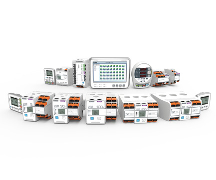
Smart Motor System
|
Accura 2700/2750
|


|
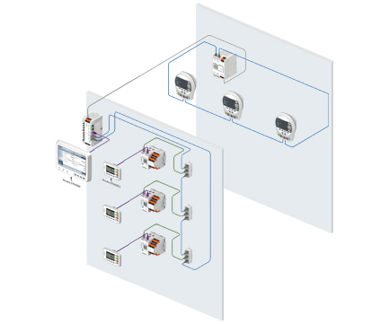
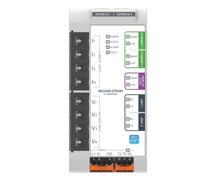
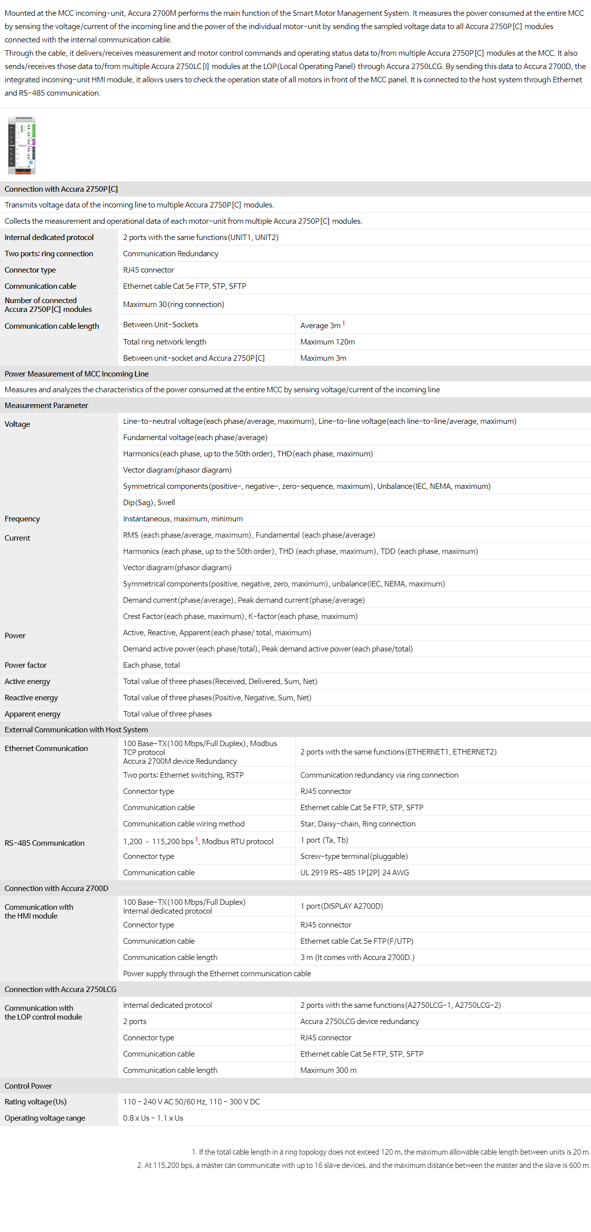
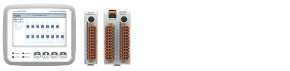
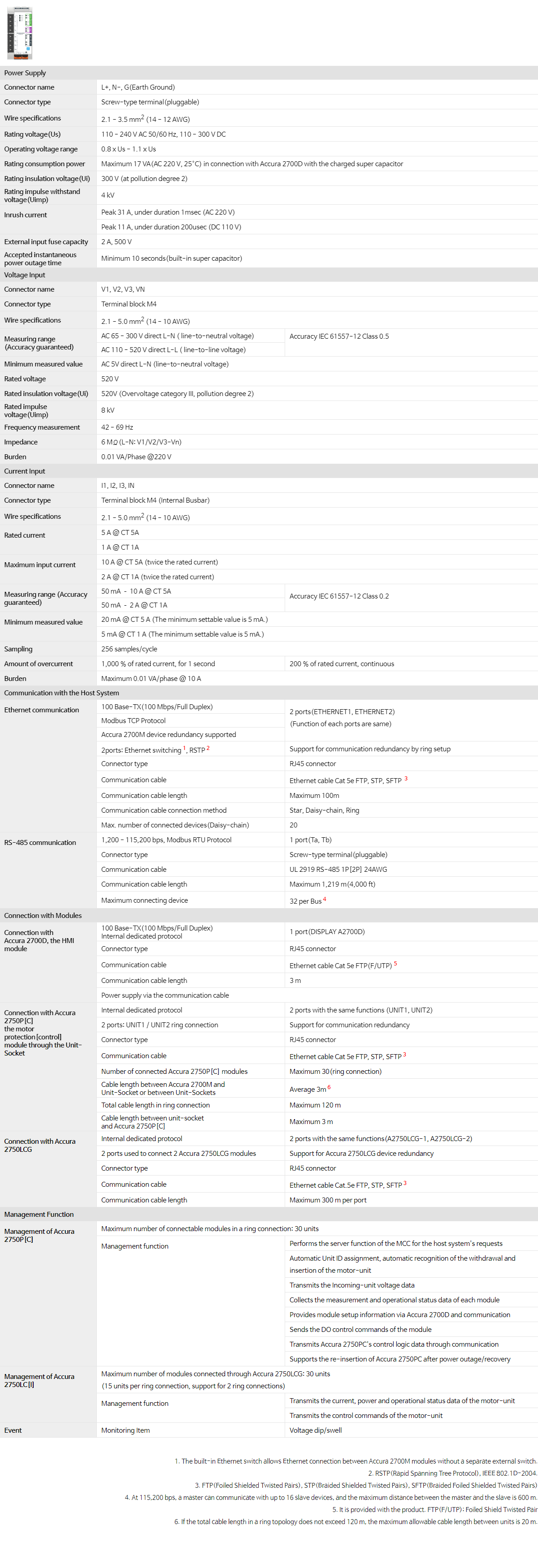
Mounted at the MCC incoming-unit, Accura 2700M performs the main function of the Smart Motor Management System. It measures the power consumed at the entire MCC by sensing the voltage/current of the incoming line and the power of the individual motor-unit by sending the sampled voltage data to all Accura 2750P[C] modules connected with the internal communication cable. Through the cable, it delivers/receives measurement and motor control commands and operating status data to/from multiple Accura 2750P[C] modules at the MCC. It also sends/receives those data to/from multiple Accura 2750LC[I] modules at the LOP(Local Operating Panel) through Accura 2750LCG. By sending this data to Accura 2700D, the integrated incoming-unit HMI module, it allows users to check the operation state of all motors in front of the MCC panel. It is connected to the host system through Ethernet and RS-485 communication. |
|||
|
|||
| Connection with Accura 2750P[C] | |||
| Transmits voltage data of the incoming line to multiple Accura 2750P[C] modules. | |||
| Collects the measurement and operational data of each motor-unit from multiple Accura 2750P[C] modules. | |||
| Internal dedicated protocol | 2 ports with the same functions(UNIT1, UNIT2) | ||
| Two ports: ring connection | Communication Redundancy | ||
| Connector type | RJ45 connector | ||
| Communication cable | Ethernet cable Cat 5e FTP, STP, SFTP | ||
|
Number of connected Accura 2750P[C] modules |
Maximum 30(ring connection) | ||
|
Communication cable length |
Between Unit-Sockets | Average 3m1 | |
| Total ring network length | Maximum 120m | ||
| Between unit-socket and Accura 2750P[C] | Maximum 3m | ||
| Power Measurement of MCC Incoming Line | |||
| Measures and analyzes the characteristics of the power consumed at the entire MCC by sensing voltage/current of the incoming line | |||
| Measurement Parameter | |||
|
Voltage |
Line-to-neutral voltage(each phase/average, maximum), Line-to-line voltage(each line-to-line/average, maximum) | ||
| Fundamental voltage(each phase/average) | |||
| Harmonics(each phase, up to the 50th order), THD(each phase, maximum) | |||
| Vector diagram(phasor diagram) | |||
| Symmetrical components(positive-, negative-, zero-sequence, maximum), Unbalance(IEC, NEMA, maximum) | |||
| Dip(Sag), Swell | |||
| Frequency | Instantaneous, maximum, minimum | ||
|
Current |
RMS (each phase/average, maximum), Fundamental (each phase/average) | ||
| Harmonics (each phase, up to the 50th order), THD (each phase, maximum), TDD (each phase, maximum) | |||
| Vector diagram(phasor diagram) | |||
| Symmetrical components(positive, negative, zero, maximum), unbalance(IEC, NEMA, maximum) | |||
| Demand current(phase/average), Peak demand current(phase/average) | |||
| Crest Factor(each phase, maximum), K-factor(each phase, maximum) | |||
|
Power |
Active, Reactive, Apparent(each phase/ total, maximum) | ||
| Demand active power(each phase/total), Peak demand active power(each phase/total) | |||
| Power factor | Each phase, total | ||
| Active energy | Total value of three phases(Received, Delivered, Sum, Net) | ||
| Reactive energy | Total value of three phases(Positive, Negative, Sum, Net) | ||
| Apparent energy | Total value of three phases | ||
| External Communication with Host System | |||
|
Ethernet Communication |
100 Base-TX(100 Mbps/Full Duplex), Modbus TCP protocol Accura 2700M device Redundancy |
2 ports with the same functions(ETHERNET1, ETHERNET2) | |
| Two ports: Ethernet switching, RSTP | Communication redundancy via ring connection | ||
| Connector type | RJ45 connector | ||
| Communication cable | Ethernet cable Cat 5e FTP, STP, SFTP | ||
| Communication cable wiring method | Star, Daisy-chain, Ring connection | ||
|
RS-485 Communication |
1,200 – 115,200 bps1, Modbus RTU protocol | 1 port (Ta, Tb) | |
| Connector type | Screw-type terminal(pluggable) | ||
| Communication cable | UL 2919 RS-485 1P[2P] 24 AWG | ||
| Connection with Accura 2700D | |||
|
Communication with the HMI module |
100 Base-TX(100 Mbps/Full Duplex) Internal dedicated protocol |
1 port(DISPLAY A2700D) | |
| Connector type | RJ45 connector | ||
| Communication cable | Ethernet cable Cat.5e FTP(F/UTP) | ||
| Communication cable length | 3 m (It comes with Accura 2700D.) | ||
| Power supply through the Ethernet communication cable | |||
| Connection with Accura 2750LCG | |||
|
Communication with the LOP control module |
Internal dedicated protocol | 2 ports with the same functions(A2750LCG-1, A2750LCG-2) | |
| 2 ports | Accura 2750LCG device redundancy | ||
| Connector type | RJ45 connector | ||
| Communication cable | Ethernet cable Cat 5e FTP, STP, SFTP | ||
| Communication cable length | Maximum 300 m | ||
| Control Power | |||
| Rating voltage(Us) | 110 - 240 V AC 50/60 Hz, 110 - 300 V DC | ||
| Operating voltage range | 0.8 x Us - 1.1 x Us | ||
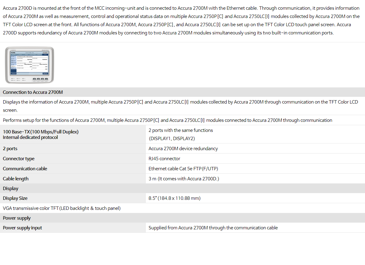
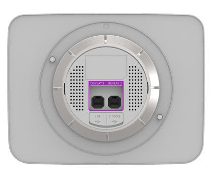
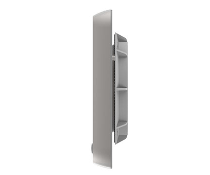
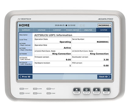
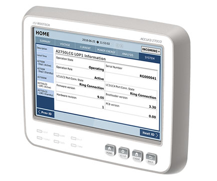
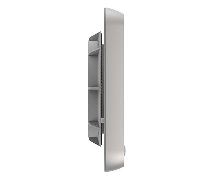
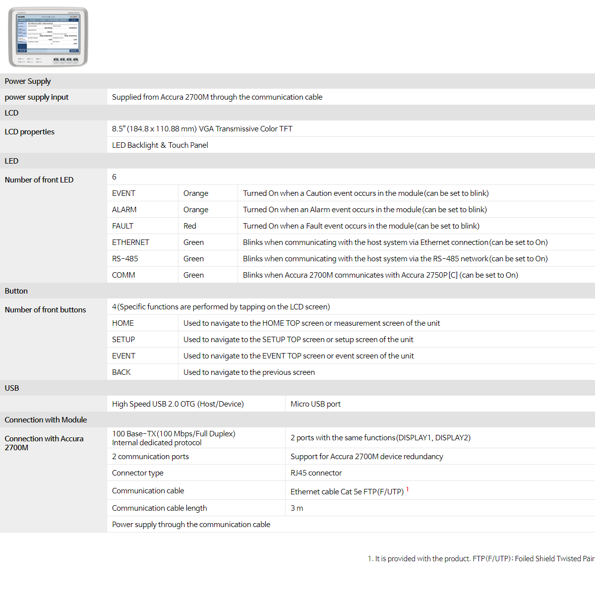
| Accura 2700D is mounted at the front of the MCC incoming-unit and is connected to Accura 2700M with the Ethernet cable. Through communication, it provides information of Accura 2700M as well as measurement, control and operational status data on multiple Accura 2750P[C] and Accura 2750LC[I] modules collected by Accura 2700M on the TFT Color LCD screen at the front. All functions of Accura 2700M, Accura 2750P[C], and Accura 2750LC[I] can be set up on the TFT Color LCD touch panel screen. Accura 2700D supports redundancy of Accura 2700M modules by connecting to two Accura 2700M modules simultaneously using its two built-in communication ports. | |||
|
|||
| Connection to Accura 2700M | |||
| Displays the information of Accura 2700M, multiple Accura 2750P[C] and Accura 2750LC[I] modules collected by Accura 2700M through communication on the TFT Color LCD screen. | |||
| Performs setup for the functions of Accura 2700M, multiple Accura 2750P[C] and Accura 2750LC[I] modules connected to Accura 2700M through communication | |||
|
100 Base-TX(100 Mbps/Full Duplex) Internal dedicated protocol |
2 ports with the same functions (DISPLAY1, DISPLAY2) |
||
| 2 ports | Accura 2700M device redundancy | ||
| Connector type | RJ45 connector | ||
| Communication cable | Ethernet cable Cat 5e FTP(F/UTP) | ||
| Cable length | 3 m (It comes with Accura 2700D.) | ||
| Display | |||
| Display Size | 8.5”(184.8 x 110.88 mm) | ||
| VGA transmissive color TFT(LED backlight & touch panel) | |||
| Power supply | |||
| Power supply input | Supplied from Accura 2700M through the communication cable | ||
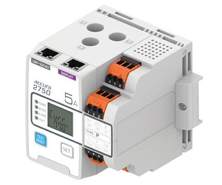
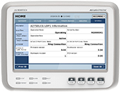
| Installed at the individual motor unit in the MCC, Accura 2750P mainly protects the motor by measuring the current supplied to the motor. It also measures the various power characteristics of the individual motor-unit based on the current signal data measured by the built-in CT and the voltage signal data received from Accura 2700M via communication. For a motor-unit driven by an inverter, it measures the various power characteristics of the individual motor unit by receiving the sampled output voltage data of the inverter processed with the Low Pass Filter(LPF) from Accura 2750INV/VOL module via communication. Accura 2750PC provides the motor control function along with the measurement and protection function of Accura 2750P. | ||

|
||
| Connection with Accura 2700M through Unit-Socket | ||
| Receives the voltage data of the incoming line from Accura 2700M. | ||
| Transmits the measurement and operating status data of the corresponding motor-unit to Accura 2700M. | ||
| Internal dedicated protocol | 1 port(UNIT-SOCKET) | |
| Connector type | RJ45 connector | |
| Communication cable | Ethernet cable Cat 5e FTP, STP, SFTP | |
| Communication cable length | Maximum 3m | |
| Power Measurement of Motor-Unit Branch Line | ||
| Measures and analyzes various power characteristics based on the voltage data received from Accura 2700M and the current data of the motor-unit branch line. | ||
| Measures and analyzes the various power characteristics of the motor-unit branch line based on the inverter output voltage data received from Accura 2750INV/VOL module. | ||
| Measurement Parameter | ||
|
Current |
RMS(each phase/average, Maximum phase/average), Fundamental(each phase/average) | |
| Harmonics (each phase, 1st – 31st order), THD (each phase, maximum), TDD (each phase, maximum) | ||
| Vector diagram(phasor diagram) | ||
| Symmetrical components(positive, negative, zero, maximum), unbalance(IEC, NEMA, maximum) | ||
| Maximum starting current (each phase/average), Maximum running current(each phase/average) | ||
| Demand(each phase/average), Peak demand(each phase/average) | ||
| Crest Factor(each phase, maximum), K-factor(each phase, maximum) | ||
|
Ground current1 |
Ground(RMS value measured by the built-in ZCT)(instantaneous, maximum) | |
| Residual ground(RMS value measured by summing up three phase current)(instantaneous, maximum) | ||
|
Power |
Active, Reactive, Apparent(each phase/total, maximum) | |
| Demand, Peak demand(each phase/total) | ||
| Power factor | Each phase, total | |
| Active energy | Total value of three phases(Received, Delivered, Sum, Net) | |
| Reactive energy | Total value of three phases(Positive, Negative, Sum, Net) | |
| Apparent energy | Total value of three phases | |
| Protection Relay of Motor | ||
| Measures current and analyzes current data for protection of the individual motor powered by the motor-unit. | ||
| Protection Item | ||
| Thermal protection | THR(49) | |
| Overcurrent protection | Time Over Current(50TD), JAM(50LR-TD), Long Start Relay(48), Instantaneous Over Current(50) Long Time Over Current(50LTD) | |
| Current unbalance protection | Unbalance(46), Phase out current relay(46), Phase sequence relay(46) | |
| Undercurrent protection | Undercurrent(37) | |
| Ground current protection | Built-in ZCT(64), Sum of 3 phase current(50G-TD) | |
| Magnetic contactor | Magnetic contactor supervision | |
| Motor Control Function(Supported only in Accura 2750PC) | ||
| Start and stop control of single/three-phase motor and monitoring of operation status | ||
| Motor control functions are available by default. However, you can use "Accura Logic" to meet your specific needs. | ||
| Starter Mode | ||
| Overload relay | Only performs the protection Relay as Accura 2750P | |
| Direct starter | Starts/stop control of motor in one direction | |
| Reversing starter | Starts/stop control of motor in both forward and reverse directions | |
| 2-speed starter | Changes the polarity of the motor for speed control | |
| 2-step starter | Changes the wiring method while starting the motor to reduce its starting current | |
| Connection to Motor-unit HMI Module Accura 2750D[C]2 | ||
| Internal protocol | 1 port(DISPLAY) | |
| Connector type | RJ45 connector | |
| Communication cable | Ethernet cable Cat 5e FTP(F/UTP) | |
| Communication cable length | 2 m (It comes with Accura 2700D[C].) | |
| Temperature Measurement | ||
| Number of the temperature measurement sensor on Accura 2750P[C] |
1 | |
| Digital Input/Output(DIO) | ||
|
Digital input |
Accura 2750P | 1 channel (external power input) |
| Accura 2750PC | 10 channels (external power input) | |
|
Digital output |
Accura 2750P | Form-A 2 channels, Form-C 1 channel |
| Accura 2750PC | Form-A 3 channels, Form-C 1 channel | |
| Control Power Supply | ||
| Rating voltage(Us) | 110-240 V AC 50/60 Hz, 110-300 V DC | |
| Operating voltage range | 0.8 x Us-1.1 x Us | |
| The main function of Accura 2750PC-ACB module is to trip the ACB by measuring the secondary current of the built-in CT in the ACB unit and operating protection relays. The Instantaneous Over Current Relay operates quickly based on the instantaneous values of sampled current signals. Other protection relays operate based on the one-cycle RMS values measured over one cycle. When the relay operates, it sends trip signals to the ACB through the fault signal and the MHT(Magnetic Holding Trigger) signal. It is possible to select the Fault or MHT signal when performing the mapping of the digital output. It also measures various power characterisctics of the ACB unit based on the measured current data and the sampled voltage data recieved from Accura 2700M via communication. General specifications for the measurements and protection relays of Accura 2750PC-ACB module are the same as those of Accura 2750PC motor-unit protection[control] module. The features of Accura 2750PC-ACB module are as follows. | ||
|
||
| ACB-Unit Protection and Power Measurements | ||
| Operates the protection relay by measuring the secondary current of the CT installed in the ACB unit | ||
| Measures and analyzes various power characteristics based on the measured current data and the sampled voltage data received from Accura 2700M via communication | ||
| Measurement Parameters1 | ||
| Measures the parameters same as those of Accura 2750PC module | ||
| ACB Protection2 | ||
| Base current setup | FLC setup | |
| Time Over Current Relay | The relay operation mode can be configured during the motor starting interval. | |
| Instantaneous Over Current Relay | The relay operates quickly when a large current flows. - It operates within 16 ms when the measured current value is 120 % of the set threshold. - It operates within 8 ms when the measured current value is 200 % of the set threshold. |
|
| Long Time Over Current Relay | The relay operates based on the inverse-time characteristic curve (cold curve of the THR). | |
| Ground Fault Relay (ZCT) | The relay operates based on the values measured by the built-in ZCT of Accura 2750PC–ACB module1 | |
| Digital Input/Output | ||
|
Digital input |
10 channels (external excitation) | |
| Externa excitation: AC 220 V or AC/DC 110 V can be selected when ordering the product. | ||
| Digital output | 3 Form-A channels, 1 Form-C channel | |
| Power Supply | ||
| Rated voltage(Us) | 110 — 240 V AC 50/60 Hz, 110 — 300 V DC | |
| Operating voltage range | 0.8 x Us — 1.1 x Us | |
| As the rated current of the motor gets higher, a larger-diameter power cable should be used. You can install Accura 2750PC-160A/250A/400A models with high current ratings, using the terminal block (separately provided) or the through-hole busbar. | ||
| Easy Installation of Accura 2750PC-160A/250A, Accura 2750PC-400A | ||
| It is possible to install the terminal block on the load side or both sides without the need for a large-diameter power cable to directly penetrate the module. | ||
| Saves space when the MCCB of the motor-unit and the through-hole busbar are connected directly. | ||
| Model | Description | |
| TM-PC-160A | Terminal block for Accura 2750PC-160A | |
| TM-PC-250A | Terminal block for Accura 2750PC-250A | |
| TM-PC-400A | Terminal block for Accura 2750PC-400A | |
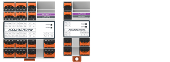
| The output voltage signal of the inverter is required to measure the inverter's output power in the motor-unit driven by the inverter. Accura 2750INV/VOL module processes the inverter output voltage with the Low Pass Filter(LPF) to generate voltage data and transmits it to Accura 2750PC module via communication. It also supports a separate RS-485 communication port to communicate with the inverter supporting RS-485 communication. By providing additional digital I/O channels, Accura 2750INV module allows for an easy-to-use, hardwired interface in connection with the inverter. | ||
|
||
| Output Voltage Measurement of the Inverter-unit | ||
| Provides voltage data by processing the inverter output voltage with the Low Pass Filter(LPF) | ||
| Frequency measurement range | 5 - 180 Hz | |
| Cut-off frequency of LPF | 188 Hz | |
| Connection with Accura 2750P[C] | ||
| Transmits the voltage data of the inverter-unit to Accura 2750P[C] via internal communication | ||
| Internal dedicated protocol | 1 port (A2750PC) | |
| Connector type | RJ45 connector | |
| Communication cable | Ethernet cable Cat.5e FTP(F/UTP) | |
| Communication cable length | 3 m (It comes with Accura 2750INV/VOL.) | |
| Connection with Motor-Unit HMI Module Accura 2750DCI | ||
| Internal dedicated protocol | 1 port (DISPLAY A2750DCI) | |
| Connector type | RJ45 connector | |
| Communication cable | Ethernet cable Cat.5e FTP(F/UTP) | |
| Communication cable length | 2 m (It comes with Accura 2750DCI.) | |
| Connection with Inverter (RS-485 communication) | ||
| Receives inverter status data and controls the inverter via RS-485 communication | ||
| Modbus RTU protocol | 1 port (Ta, Tb, SG) | |
| Connector type | Screw-type terminal (pluggable) | |
| Communication cable | UL2919 RS-485 1P[2P] 24AWG | |
| Digital Input/Output | ||
| Digital input | Accura 2750INV | 5 channels (external excitation) |
|
Digital output |
Accura 2750INV | 9 Form-A channels |
| Accura 2750VOL | 1 Form-C channel | |
| Power Supply | ||
| Rated voltage(Us) | 110 — 240 V AC 50/60 Hz, 110 — 300 V DC | |
| Operating voltage range | 0.8 x Us - 1.1 x Us | |
|
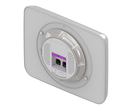
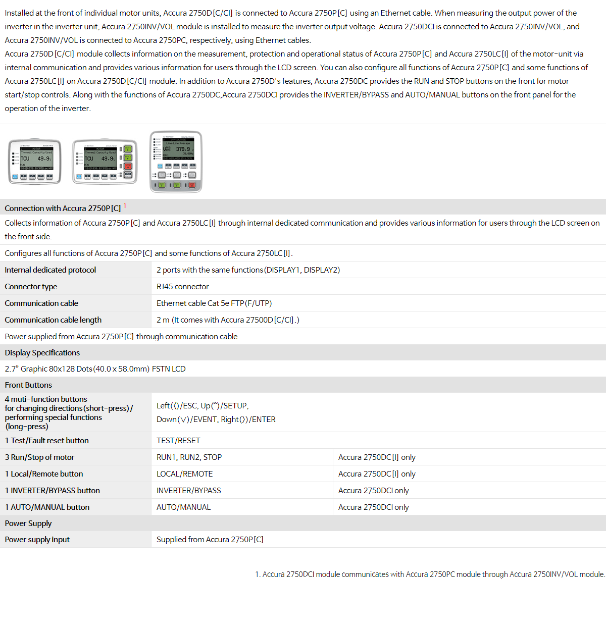
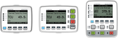
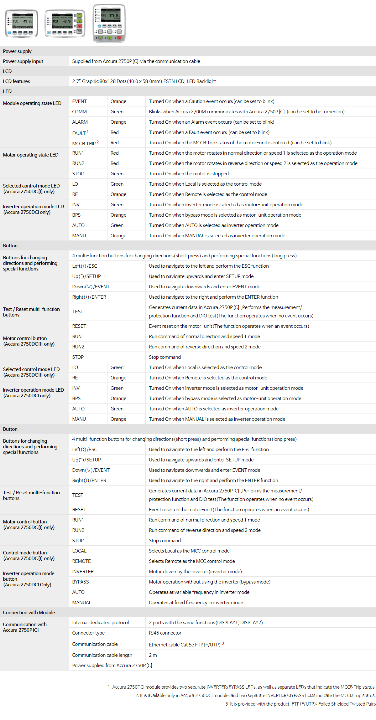
Installed at the front of individual motor units, Accura 2750D[C/CI] is connected to Accura 2750P[C] using an Ethernet cable. When measuring the output power of the inverter in the inverter unit, Accura 2750INV/VOL module is installed to measure the inverter output voltage. Accura 2750DCI is connected to Accura 2750INV/VOL, and Accura 2750INV/VOL is connected to Accura 2750PC, respectively, using Ethernet cables. Accura 2750D[C/CI] module collects information on the measurement, protection and operational status of Accura 2750P[C] and Accura 2750LC[I] of the motor-unit via internal communication and provides various information for users through the LCD screen. You can also configure all functions of Accura 2750P[C] and some functions of Accura 2750LC[I] on Accura 2750D[C/CI] module. In addition to Accura 2750D's features, Accura 2750DC provides the RUN and STOP buttons on the front for motor start/stop controls. Along with the functions of Accura 2750DC,Accura 2750DCI provides the INVERTER/BYPASS and AUTO/MANUAL buttons on the front panel for the operation of the inverter. |
||
|
||
| Connection with Accura 2750P[C]1 | ||
| Collects information of Accura 2750P[C] and Accura 2750LC[I] through internal dedicated communication and provides various information for users through the LCD screen on the front side. | ||
| Configures all functions of Accura 2750P[C] and some functions of Accura 2750LC[I]. | ||
| Internal dedicated protocol | 2 ports with the same functions(DISPLAY1, DISPLAY2) | |
| Connector type | RJ45 connector | |
| Communication cable | Ethernet cable Cat 5e FTP(F/UTP) | |
| Communication cable length | 2 m (It comes with Accura 27500D[C/CI].) | |
| Power supplied from Accura 2750P[C] through communication cable | ||
| Display Specifications | ||
| 2.7” Graphic 80x128 Dots(40.0 x 58.0mm) FSTN LCD | ||
| Front Buttons | ||
| 4 muti-function buttons for changing directions(short-press)/ performing special functions (long-press) |
Left(<)/ESC, Up(^)/SETUP, Down(∨)/EVENT, Right(>)/ENTER |
|
| 1 Test/Fault reset button | TEST/RESET | |
| 3 Run/Stop of motor | RUN1, RUN2, STOP | Accura 2750DC[I] only |
| 1 Local/Remote button | LOCAL/REMOTE | Accura 2750DC[I] only |
| 1 INVERTER/BYPASS button | INVERTER/BYPASS | Accura 2750DCI only |
| 1 AUTO/MANUAL button | AUTO/MANUAL | Accura 2750DCI only |
| Power Supply | ||
| Power supply input | Supplied from Accura 2750P[C] | |
|
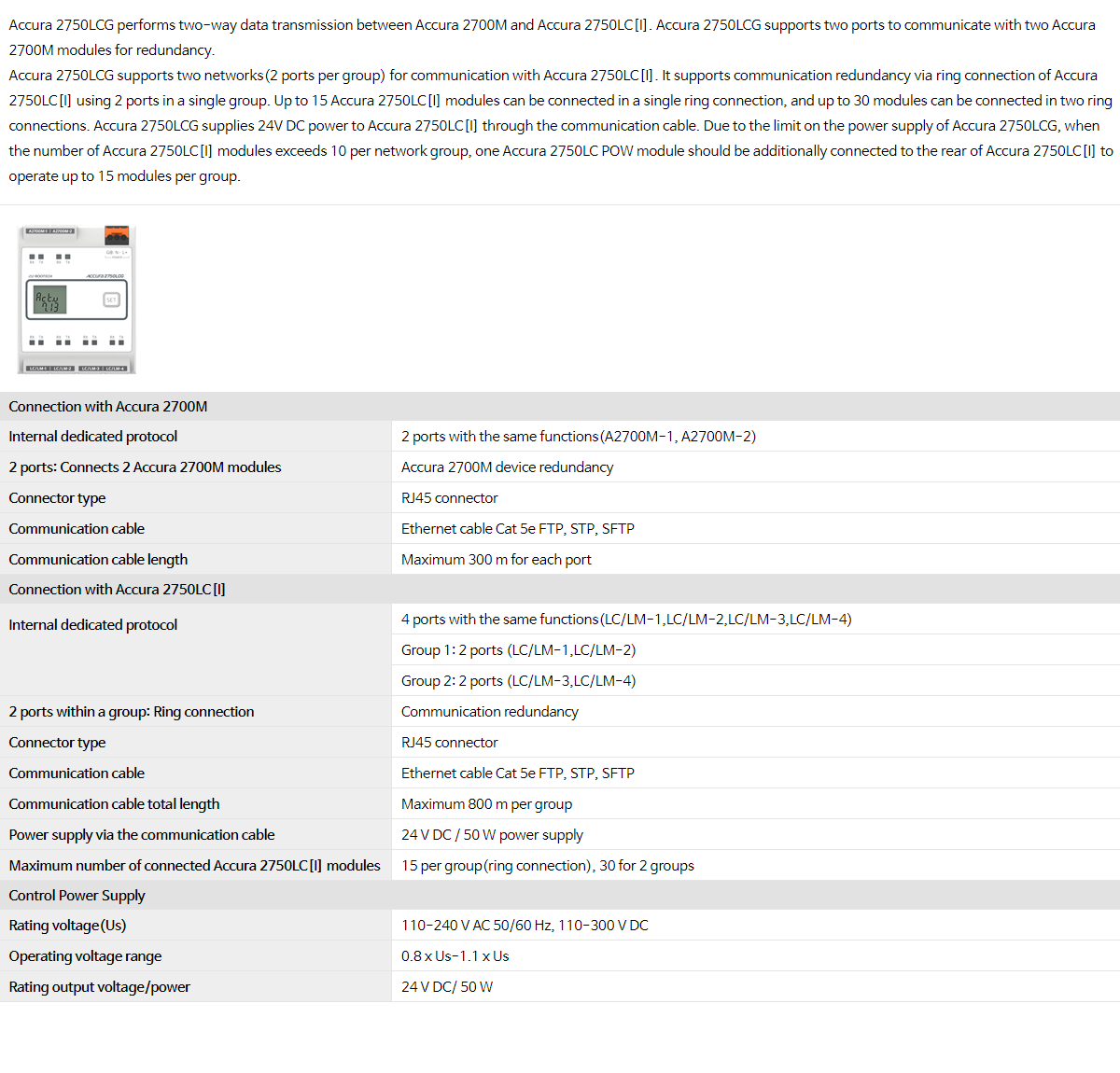
Accura 2750LCG performs two-way data transmission between Accura 2700M and Accura 2750LC[I]. Accura 2750LCG supports two ports to communicate with two Accura 2700M modules for redundancy. Accura 2750LCG supports two networks(2 ports per group) for communication with Accura 2750LC[I]. It supports communication redundancy via ring connection of Accura 2750LC[I] using 2 ports in a single group. Up to 15 Accura 2750LC[I] modules can be connected in a single ring connection, and up to 30 modules can be connected in two ring connections. Accura 2750LCG supplies 24V DC power to Accura 2750LC[I] through the communication cable. Due to the limit on the power supply of Accura 2750LCG, when the number of Accura 2750LC[I] modules exceeds 10 per network group, one Accura 2750LC POW module should be additionally connected to the rear of Accura 2750LC[I] to operate up to 15 modules per group. |
||
|
||
| Connection with Accura 2700M | ||
| Internal dedicated protocol | 2 ports with the same functions(A2700M-1, A2700M-2) | |
| 2 ports: Connects 2 Accura 2700M modules | Accura 2700M device redundancy | |
| Connector type | RJ45 connector | |
| Communication cable | Ethernet cable Cat 5e FTP, STP, SFTP | |
| Communication cable length | Maximum 300 m for each port | |
| Connection with Accura 2750LC[I] | ||
|
Internal dedicated protocol |
4 ports with the same functions(LC/LM-1,LC/LM-2,LC/LM-3,LC/LM-4) | |
| Group 1: 2 ports (LC/LM-1,LC/LM-2) | ||
| Group 2: 2 ports (LC/LM-3,LC/LM-4) | ||
| 2 ports within a group: Ring connection | Communication redundancy | |
| Connector type | RJ45 connector | |
| Communication cable | Ethernet cable Cat 5e FTP, STP, SFTP | |
| Communication cable total length | Maximum 800 m per group | |
| Power supply via the communication cable | 24 V DC / 50 W power supply | |
| Maximum number of connected Accura 2750LC[I] modules | 15 per group(ring connection), 30 for 2 groups | |
| Control Power Supply | ||
| Rating voltage(Us) | 110—240 V AC 50/60 Hz, 110—300 V DC | |
| Operating voltage range | 0.8 x Us-1.1 x Us | |
| Rating output voltage/power | 24 V DC/ 50 W | |
|
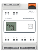
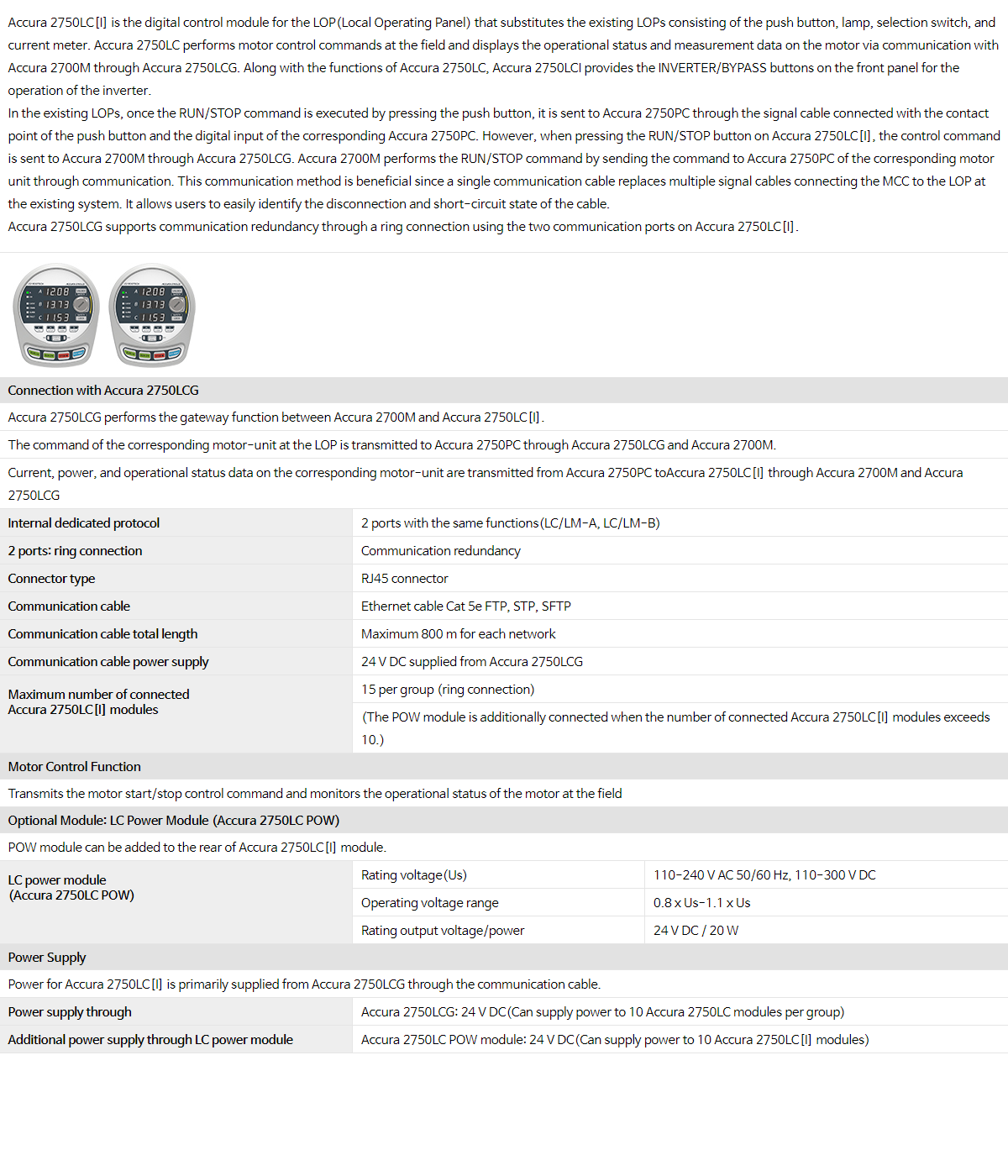
Accura 2750LC[I] is the digital control module for the LOP(Local Operating Panel) that substitutes the existing LOPs consisting of the push button, lamp, selection switch, and current meter. Accura 2750LC performs motor control commands at the field and displays the operational status and measurement data on the motor via communication with Accura 2700M through Accura 2750LCG. Along with the functions of Accura 2750LC, Accura 2750LCI provides the INVERTER/BYPASS buttons on the front panel for the operation of the inverter. In the existing LOPs, once the RUN/STOP command is executed by pressing the push button, it is sent to Accura 2750PC through the signal cable connected with the contact point of the push button and the digital input of the corresponding Accura 2750PC. However, when pressing the RUN/STOP button on Accura 2750LC[I], the control command is sent to Accura 2700M through Accura 2750LCG. Accura 2700M performs the RUN/STOP command by sending the command to Accura 2750PC of the corresponding motor unit through communication. This communication method is beneficial since a single communication cable replaces multiple signal cables connecting the MCC to the LOP at the existing system. It allows users to easily identify the disconnection and short-circuit state of the cable. Accura 2750LCG supports communication redundancy through a ring connection using the two communication ports on Accura 2750LC[I]. |
||
|
||
| Connection with Accura 2750LCG | ||
| Accura 2750LCG performs the gateway function between Accura 2700M and Accura 2750LC[I]. | ||
| The command of the corresponding motor-unit at the LOP is transmitted to Accura 2750PC through Accura 2750LCG and Accura 2700M. | ||
| Current, power, and operational status data on the corresponding motor-unit are transmitted from Accura 2750PC toAccura 2750LC[I] through Accura 2700M and Accura 2750LCG | ||
| Internal dedicated protocol | 2 ports with the same functions(LC/LM-A, LC/LM-B) | |
| 2 ports: ring connection | Communication redundancy | |
| Connector type | RJ45 connector | |
| Communication cable | Ethernet cable Cat 5e FTP, STP, SFTP | |
| Communication cable total length | Maximum 800 m for each network | |
| Communication cable power supply | 24 V DC supplied from Accura 2750LCG | |
|
Maximum number of connected
Accura 2750LC[I] modules |
15 per group (ring connection) | |
| (The POW module is additionally connected when the number of connected Accura 2750LC[I] modules exceeds 10.) | ||
| Motor Control Function | ||
| Transmits the motor start/stop control command and monitors the operational status of the motor at the field | ||
| Optional Module: LC Power Module (Accura 2750LC POW) | ||
| POW module can be added to the rear of Accura 2750LC[I] module. | ||
|
LC power module (Accura 2750LC POW) |
Rating voltage(Us) | 110-240 V AC 50/60 Hz, 110-300 V DC |
| Operating voltage range | 0.8 x Us-1.1 x Us | |
| Rating output voltage/power | 24 V DC / 20 W | |
| Power Supply | ||
| Power for Accura 2750LC[I] is primarily supplied from Accura 2750LCG through the communication cable. | ||
| Power supply through |
Accura 2750LCG: 24 V DC(Can supply power to 10 Accura 2750LC modules per group) | |
| Additional power supply through LC power module | Accura 2750LC POW module: 24 V DC(Can supply power to 10 Accura 2750LC[I] modules) | |
|
||
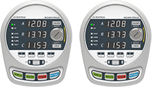
| Accura 2750LM Logic Control Module | ||
|
Option
|
-DC24V | Power supply DC 24 V, digital input DC 24 V |
| -DC110V | Power supply DC 110 V, digital input DC 110 V | |
|
Description
|
RS-485 or Ethernet communication with host system | |
| Digital input/output, 18 DI channels, 9 DO channels provided | ||
| Accura 2750IO module expansion connection | ||
| Accura 2750LD HMI module connection | ||
| Accura 2750LD HMI Module for Logic Control | ||
|
Description
|
4 buttons and 5-inch color TFT LCD (with touch panel) | |
| Setup, control, status monitoring | ||
| Accura 2750IO IO Module | ||
| Accura 2750IO-DI2 | ||
|
Option
|
-DC24V | Digital input DC 24 V |
| -DC110V | Digital input DC 110 V | |
| Description | Digital input, 22 channels | |
| Accura 2750IO-DO1 | ||
| Description | Digital output, 6 channels | |
| Accura 2750IO-DO2 | ||
| Description | Digital output, 12 channels | |
| Accura 2750IO-AI1 | ||
|
Description
|
Analog input, DC current 4 - 20/ 0 - 20 mA | |
| 6 channels | ||
| Accura 2750IO-RTD2 | ||
|
Description
|
Analog input, Temperature measurement via RTD sensor | |
| 8 channels | ||
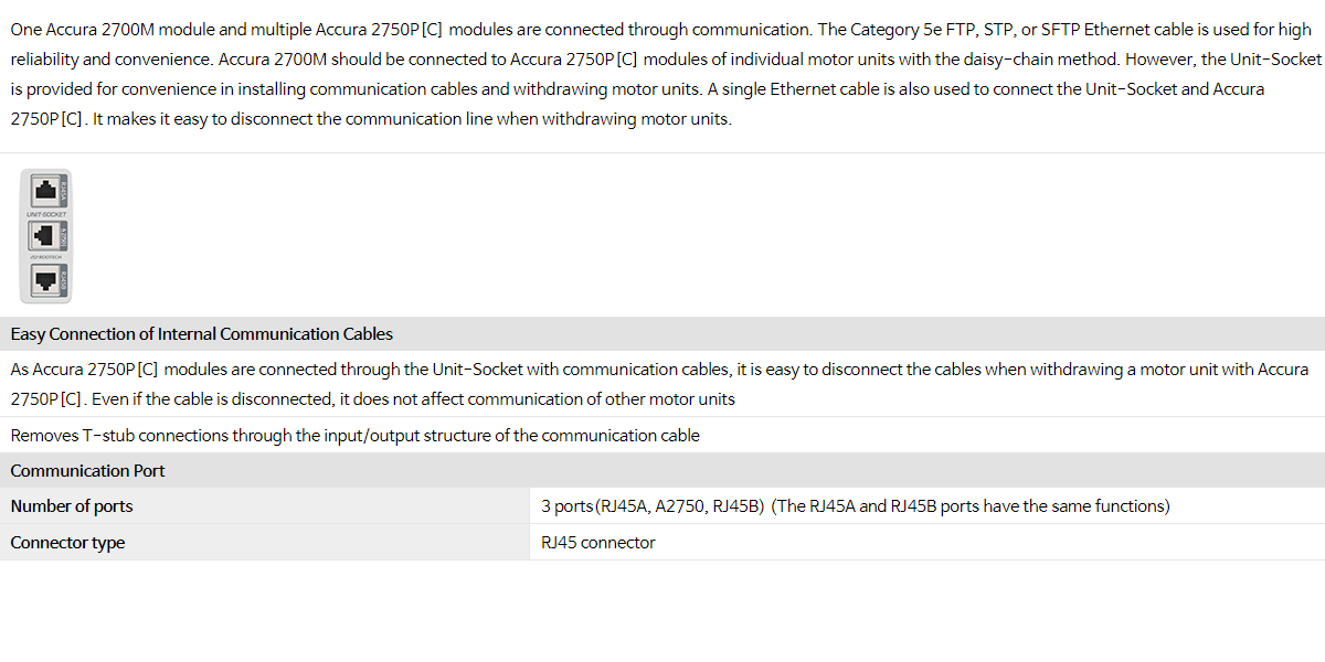
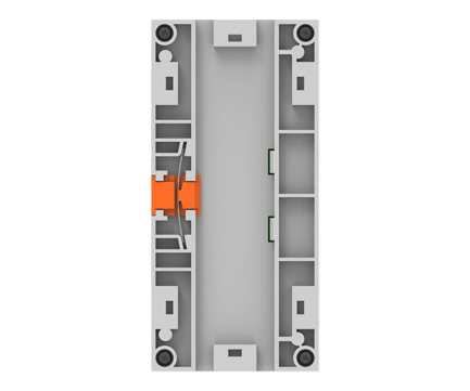
| One Accura 2700M module and multiple Accura 2750P[C] modules are connected through communication. The Category 5e FTP, STP, or SFTP Ethernet cable is used for high reliability and convenience. Accura 2700M should be connected to Accura 2750P[C] modules of individual motor units with the daisy-chain method. However, the Unit-Socket is provided for convenience in installing communication cables and withdrawing motor units. A single Ethernet cable is also used to connect the Unit-Socket and Accura 2750P[C]. It makes it easy to disconnect the communication line when withdrawing motor units. | ||
|
||
| Easy Connection of Internal Communication Cables | ||
| As Accura 2750P[C] modules are connected through the Unit-Socket with communication cables, it is easy to disconnect the cables when withdrawing a motor unit with Accura 2750P[C]. Even if the cable is disconnected, it does not affect communication of other motor units | ||
| Removes T-stub connections through the input/output structure of the communication cable | ||
| Communication Port | ||
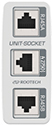
| Number of ports | 3 ports(RJ45A, A2750, RJ45B) (The RJ45A and RJ45B ports have the same functions) | |
| Connector type | RJ45 connector | |
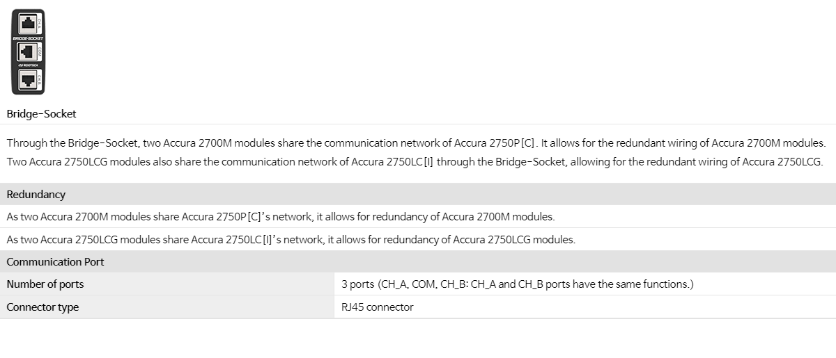
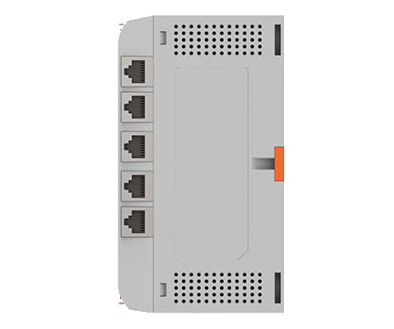
| Through the Bridge-Socket, two Accura 2700M modules share the communication network of Accura 2750P[C]. It allows for the redundant wiring of Accura 2700M modules. Two Accura 2750LCG modules also share the communication network of Accura 2750LC[I] through the Bridge-Socket, allowing for the redundant wiring of Accura 2750LCG. | ||
|
||
| Redundancy | ||
| As two Accura 2700M modules share Accura 2750P[C]’s network, it allows for redundancy of Accura 2700M modules. | As two Accura 2750LCG modules share Accura 2750LC[I]’s network, it allows for redundancy of Accura 2750LCG modules. | |
| Communication Port | ||
|
Number of ports |
3 ports(CH_A, COM, CH_B) | |
| (The CH_A and CH_B ports have the same functions) | ||
| Connector type | RJ45 connector | |
| Power Supply | ||
| Connector name | L+, N-, G(Earth Ground) | |
| Connector type | Screw-type terminal(pluggable) | |
| Wire specifications | 2.1 — 3.5 mm2 (14 — 12 AWG) | |
| Rating voltage(Us) | 110 — 240 V AC 50/60 Hz, 110 — 300 V DC | |
| Operating voltage range | 0.8 x Us - 1.1 x Us | |
| Rating consumption power | Maximum 17 VA(AC 220 V, 25°C) in connection with Accura 2700D with the charged super capacitor | |
| Rating insulation voltage(Ui) | 300 V (at pollution degree 2) | |
| Rating impulse withstand voltage(Uimp) | 4 kV | |
|
Inrush current |
Peak 31 A, under duration 1msec (AC 220 V) | |
| Peak 11 A, under duration 200usec (DC 110 V) | ||
| External input fuse capacity | 2 A, 500 V | |
| Accepted instantaneous power outage time | Minimum 10 seconds(built-in super capacitor) | |
| Voltage Input | ||
| Connector name | V1, V2, V3, VN | |
| Connector type | Terminal block M4 | |
| Wire specifications | 2.1 — 5.0 mm2 (14 — 10 AWG) | |
|
Measuring range (Accuracy guaranteed) |
AC 65 - 300 V direct L-N ( line-to-neutral voltage) | Accuracy IEC 61557-12 Class 0.5 |
| AC 110 — 520 V direct L-L ( line-to-line voltage) | ||
| Minimum measured value | AC 5V direct L-N (line-to-neutral voltage) | |
| Rated voltage | 520 V | |
| Rated insulation voltage(Ui) | 520V (Overvoltage category III, pollution degree 2) | |
| Rated impulse voltage(Uimp) | 8 kV | |
| Frequency measurement | 42 — 69 Hz | |
| Impedance | 6 MΩ(L-N: V1/V2/V3-Vn) | |
| Burden | 0.01 VA/Phase @220 V | |
| Current Input | ||
| Connector name | I1, I2, I3, IN | |
| Connector type | Terminal block M4 (Internal Busbar) | |
| Wire specifications | 2.1 — 5.0 mm2 (14 — 10 AWG) | |
|
Rated current
|
5 A @ CT 5A | |
| 1 A @ CT 1A | ||
|
Maximum input current
|
10 A @ CT 5A (twice the rated current) | |
| 2 A @ CT 1A (twice the rated current) | ||
|
Measuring range (Accuracy guaranteed)
|
50 mA – 10 A @ CT 5A |
Accuracy IEC 61557-12 Class 0.2
|
| 50 mA – 2 A @ CT 1A | ||
|
Minimum measured value
|
20 mA @ CT 5 A (The minimum settable value is 5 mA.) | |
| 5 mA @ CT 1 A (The minimum settable value is 5 mA.) | ||
| Sampling | 256 samples/cycle | |
| Amount of overcurrent | 1,000 % of rated current, for 1 second | 200 % of rated current, continuous |
| Burden | Maximum 0.01 VA/phase @ 10 A | |
| Communication with the Host System | ||
|
Ethernet communication |
100 Base-TX(100 Mbps/Full Duplex) |
2 ports(ETHERNET1, ETHERNET2)
(Function of each ports are same) |
| Modbus TCP Protocol | ||
| Accura 2700M device redundancy supported | ||
| 2ports: Ethernet switching1, RSTP2 | Support for communication redundancy by ring setup | |
| Connector type | RJ45 connector | |
| Communication cable | Ethernet cable Cat 5e FTP, STP, SFTP 3 | |
| Communication cable length | Maximum 100m | |
| Communication cable connection method | Star, Daisy-chain, Ring | |
| Max. number of connected devices(Daisy-chain) | 20 | |
|
RS-485 communication |
1,200 - 115,200 bps, Modbus RTU Protocol | 1 port(Ta, Tb) |
| Connector type | Screw-type terminal(pluggable) | |
| Communication cable | UL 2919 RS-485 1P[2P] 24AWG | |
| Communication cable length | Maximum 1,219 m(4,000 ft) | |
| Maximum connecting device | 32 per Bus4 | |
| Connection with Modules | ||
|
Connection with Accura 2700D, the HMI module |
100 Base-TX(100 Mbps/Full Duplex) Internal dedicated protocol |
1 port(DISPLAY A2700D) |
| Connector type | RJ45 connector | |
| Communication cable | Ethernet cable Cat 5e FTP(F/UTP)5 | |
| Communication cable length | 3 m | |
| Power supply via the communication cable | ||
|
Connection with Accura 2750P[C] the motor protection[control] module through the Unit-Socket |
Internal dedicated protocol | 2 ports with the same functions (UNIT1, UNIT2) |
| 2 ports: UNIT1 / UNIT2 ring connection | Support for communication redundancy | |
| Connector type | RJ45 connector | |
| Communication cable | Ethernet cable Cat 5e FTP, STP, SFTP3 | |
| Number of connected Accura 2750P[C] modules | Maximum 30(ring connection) | |
| Cable length between Accura 2700M and Unit-Socket or between Unit-Sockets |
Average 3m6 | |
| Total cable length in ring connection | Maximum 120 m | |
| Cable length between unit-socket and Accura 2750P[C] |
Maximum 3 m | |
|
Connection with Accura 2750LCG |
Internal dedicated protocol | 2 ports with the same functions(A2750LCG-1, A2750LCG-2) |
| 2 ports used to connect 2 Accura 2750LCG modules | Support for Accura 2750LCG device redundancy | |
| Connector type | RJ45 connector | |
| Communication cable | Ethernet cable Cat.5e FTP, STP, SFTP3 | |
| Communication cable length | Maximum 300 m per port | |
| Management Function | ||
|
Management of Accura 2750P[C] |
Maximum number of connectable modules in a ring connection: 30 units | |
|
Management function |
Performs the server function of the MCC for the host system's requests | |
| Automatic Unit ID assignment, automatic recognition of the withdrawal and insertion of the motor-unit | ||
| Transmits the Incoming-unit voltage data | ||
| Collects the measurement and operational status data of each module | ||
| Provides module setup information via Accura 2700D and communication | ||
| Sends the DO control commands of the module | ||
| Transmits Accura 2750PC's control logic data through communication | ||
| Supports the re-insertion of Accura 2750PC after power outage/recovery | ||
|
Management of Accura 2750LC[I] |
Maximum number of modules connected through Accura 2750LCG: 30 units (15 units per ring connection, support for 2 ring connections) |
|
|
Management function |
Transmits the current, power and operational status data of the motor-unit | |
| Transmits the control commands of the motor-unit | ||
| Event | Monitoring Item | Voltage dip/swell |
| Power Supply | |||
| power supply input | Supplied from Accura 2700M through the communication cable | ||
| LCD | |||
|
LCD properties |
8.5”(184.8 x 110.88 mm) VGA Transmissive Color TFT | ||
| LED Backlight & Touch Panel | |||
| LED | |||
|
Number of front LED |
6 | ||
| EVENT | Orange | Turned On when a Caution event occurs in the module(can be set to blink) | |
| ALARM | Orange | Turned On when an Alarm event occurs in the module(can be set to blink) | |
| FAULT | Red | Turned On when a Fault event occurs in the module(can be set to blink) | |
| ETHERNET | Green | Blinks when communicating with the host system via Ethernet connection(can be set to On) | |
| RS-485 | Green | Blinks when communicating with the host system via the RS-485 network(can be set to On) | |
| COMM | Green | Blinks when Accura 2700M communicates with Accura 2750P[C](can be set to On) | |
| Button | |||
|
Number of front buttons |
4(Specific functions are performed by tapping on the LCD screen) | ||
| HOME | Used to navigate to the HOME TOP screen or measurement screen of the unit | ||
| SETUP | Used to navigate to the SETUP TOP screen or setup screen of the unit | ||
| EVENT | Used to navigate to the EVENT TOP screen or event screen of the unit | ||
| BACK | Used to navigate to the previous screen | ||
| USB | |||
| High Speed USB 2.0 OTG (Host/Device) | Micro USB port | ||
| Connection with Module | |||
|
Connection with Accura 2700M |
100 Base-TX(100 Mbps/Full Duplex) Internal dedicated protocol |
2 ports with the same functions(DISPLAY1, DISPLAY2) | |
| 2 communication ports | Support for Accura 2700M device redundancy | ||
| Connector type | RJ45 connector | ||
| Communication cable | Ethernet cable Cat 5e FTP(F/UTP)1 | ||
| Communication cable length | 3 m | ||
| Power supply through the communication cable | |||
| Power supply | |||
| Power supply input | Supplied from Accura 2750P[C] via the communication cable | ||
| LCD | |||
| LCD features | 2.7” Graphic 80x128 Dots(40.0 x 58.0mm) FSTN LCD, LED Backlight | ||
| LED | |||
|
Module operating state LED |
EVENT | Orange | Turned On when a Caution event occurs(can be set to blink) |
| COMM | Green | Blinks when Accura 2700M communicates with Accura 2750P[C] (can be set to be turned on) | |
| ALARM | Orange | Turned On when an Alarm event occurs (can be set to blink) | |
| FAULT1 | Red | Turned On when a Fault event occurs (can be set to blink) | |
| MCCB TRIP2 | Red | Turned On when the MCCB Trip status of the motor-unit is entered (can be set to blink) | |
|
Motor operating state LED |
RUN1 | Red | Turned On when the motor rotates in normal direction or speed 1 is selected as the operation mode |
| RUN2 | Red | Turned On when the motor rotates in reverse direction or speed 2 is selected as the operation mode | |
| STOP | Green | Turned On when the motor is stopped | |
|
Selected control mode LED (Accura 2750DC[I] only) |
LO | Green | Turned On when Local is selected as the control mode |
| RE | Orange | Turned On when Remote is selected as the control mode | |
|
Inverter operation mode LED (Accura 2750DCI only) |
INV | Green | Turned On when inverter mode is selected as motor-unit operation mode |
| BPS | Orange | Turned On when bypass mode is selected as motor-unit operation mode | |
| AUTO | Green | Turned On when AUTO is selected as inverter operation mode | |
| MANU | Orange | Turned On when MANUAL is selected as inverter operation mode | |
| Button | |||
|
Buttons for changing directions and performing special functions |
4 multi-function buttons for changing directions(short press) and performing special functions(long press) | ||
| Left(<)/ESC | Used to navigate to the left and perform the ESC function | ||
| Up(^)/SETUP | Used to navigate upwards and enter SETUP mode | ||
| Down(∨)/EVENT | Used to navigate downwards and enter EVENT mode | ||
| Right(>)/ENTER | Used to navigate to the right and perform the ENTER function | ||
|
Test / Reset multi-function buttons |
TEST | Generates current data in Accura 2750P[C] ,Performs the measurement/ protection function and DIO test(The function operates when no event occurs) |
|
| RESET | Event reset on the motor-unit(The function operates when an event occurs) | ||
|
Motor control button (Accura 2750DC[I] only) |
RUN1 | Run command of normal direction and speed 1 mode | |
| RUN2 | Run command of reverse direction and speed 2 mode | ||
| STOP | Stop command | ||
|
Control mode button (Accura 2750DC[I] only) |
LOCAL | Selects Local as the MCC control model | |
| REMOTE | Selects Remote as the MCC control mode | ||
|
Inverter operation mode button (Accura 2750DCI Only) |
INVERTER | Motor driven by the inverter(inverter mode) | |
| BYPASS | Motor operation without using the inverter(bypass mode) | ||
| AUTO | Operates at variable frequency in inverter mode | ||
| MANUAL | Operates at fixed frequency in inverter mode | ||
| Connection with Module | |||
|
Communication with
Accura 2750P[C] |
Internal dedicated protocol | 2 ports with the same functions(DISPLAY1, DISPLAY2) | |
| Connector type | RJ45 connector | ||
| Communication cable | Ethernet cable Cat 5e FTP(F/UTP)3 | ||
| Communication cable length | 2 m | ||
| Power supplied from Accura 2750P[C] | |||
| Power Supply | |||
| Connector name | L+, N-, G(Earth Ground) | ||
| Connector type | Screw-type terminal(Pluggable) | ||
| Wire specifications | 2.1 — 3.5 mm2 (14 — 12 AWG) | ||
| Rating voltage(Us) | 110 — 240 V AC 50/60 Hz, 110 — 300 V DC | ||
| Operating voltage range | 0.8 x Us — 1.1 x Us | ||
| Rating consumption power | Maximum 13 VA(AC 220 V, 25°C) @Super Capacitor charging and full digital output operating | ||
| Rating insulation voltage(Ui) | 300 V(at pollution degree 2) | ||
| Rating impulse withstand voltage(Uimp) | 4 kV | ||
|
Inrush current |
Peak 40 A, Under duration 400 usec (AC 220 V) | ||
| Peak 18 A, Under duration 200 usec (DC 110 V) | |||
| Input external fuse capacity | 2 A, 500 V | ||
| Accepted instantaneous power outage time | Minimum 10 seconds(built-in super capacitor) | ||
| Voltage Input | |||
|
Voltage input |
Receives voltage data from Accura 2700M through communication | ||
| Receives the inverter output voltage data from Accura 2750INV/VOL through communication for the motor-unit driven by the inverter | |||
| Current Input | |||
| Connector type | Through-hole type | ||
| Sampling | 64 samples/ cycle | ||
|
Outer hole diameter |
Accura 2750P[C]-5A/30A | Ø12 mm | |
| Accura 2750P[C]-100A | Ø19 mm | ||
| Accura 2750PC-160A/250A | Ø25 mm | ||
| Accura 2750PC-400A | Ø30 mm | ||
|
Rated current |
Accura 2750P[C]-5A | 5 A | |
| Accura 2750P[C]-30A | 30 A | ||
| Accura 2750P[C]-100A | 100 A | ||
| Accura 2750PC-160A | 160 A | ||
| Accura 2750PC-250A | 250 A | ||
| Accura 2750PC-400A | 400 A | ||
|
Motor FLC Setup Range |
Accura 2750P[C]-5A | 0.50 — 5 A | |
| Accura 2750P[C]-30A | 3.0 — 30 A | ||
| Accura 2750P[C]-100A | 10.0 — 100 A | ||
| Accura 2750PC-160A | 16.0 — 160.0 A | ||
| Accura 2750PC-250A | 25.0 — 250.0 A | ||
| Accura 2750PC-400A | 40.0 — 400.0 A | ||
| Digital Input | |||
|
Number of channels |
Accura 2750P | 1 channel(external excitation) | |
| Accura 2750PC | 10 channels(external excitation) | ||
| Connector type | Screw-type terminal(pluggable) | ||
| Wire specification | 0.21 — 3.5 mm2 (24 — 12AWG) | ||
|
Insulation method |
Insulated between groups, uninsulated within a group | ||
| Group 1: channel 1-5 (1DI1- 1DI5) 1DIG common | |||
| Group 2: channel 6-10 (2DI6- 2DI10) 2DIG common | |||
| Minimum pulse width | 50 msec | ||
| Input type | External excitation | ||
| External Power Supply Options | AC220 V | AC/DC110 V | Note |
|
Input Impedance
|
66 kΩ | Not applicable | for Accura 2750P1 |
| 405 kΩ | 225 kΩ | for Accura 2750PC | |
| Low voltage range | 0 — 140 Vac | 0 — 55 Vac/Vdc | - |
| High voltage range | 165 — 240 Vac | 78 — 130 Vac/Vdc | - |
| Digital Output | |||
|
Number of channels / Output form |
Accura 2750P | 3 channels(Form-A 2 channels, Form-C 1 channel) | |
| Accura 2750PC | 4 channels(Form-A 3 channels, Form-C 1 channel) | ||
| Connector type | Screw-type terminal(pluggable) | ||
| Wire specification | 1.5 — 3.5 mm2(16 — 12AWG) | ||
| Insulation | AC 2,000 V/for 1 minute. | ||
|
Output rating |
Form-A: 5 A/250 Vac, 5A/30 Vdc(DO1 – DO3) | ||
| Form-C: 3 A/250 Vac, 3A/30 Vdc(DO4) | |||
| LCD | |||
| LCD features | 1.2”(24.5 x 21.0mm) Customized Mono LCD, LED Backlight | ||
| Connection with Module | |||
|
RS-485 communication with motor protection[control] module using Unit-Socket |
Internal dedicated protocol | 1port(UNIT-SOCKET) | |
| Connector type | RJ45 connector | ||
| Communication cable | Ethernet cable Cat.5e FTP, STP, SFTP1 | ||
| Communication cable length | Maximum 3 m | ||
|
RS-485 communication with Accura 2750D[C] HMI module |
Internal dedicated protocol | 1 port(DISPLAY) | |
| Connector type | RJ45 connector | ||
| Communication cable | Ethernet cable Cat.5e FTP(F/UTP)2 | ||
| Communication cable length | 2 m | ||
| Temperature Measurement4 | |||
| Temperature measurement range | -20 – 100°C | ||
| Accuracy | ±2% Full Scale (Full Scale: 100°C) | ||
| Motor Protection Relay | |||
| Thermal Relay (THR) | IEC 60255-149 | ||
| Overcurrent Relay (OCR) | Definite time | ||
| Phase Out Current Relay(POCR) | Instantaneous characteristic(in 200ms) | ||
| Phase Sequence Relay (PSR) | Definite time | ||
| Unbalance Current Relay (UBCR) | Definite time | ||
| Long Start Relay (LSR) | Definite time | ||
| Jam Relay (JAM) | Definite time | ||
| Ground current fault Relay (GR) by ZCT Current |
Definite time | ||
| Residual Ground current fault Relay (GR) by sum of 3-phase current |
Definite time | ||
| Under Current Relay (UCR) | Definite time | ||
| Instantaneous Over Current Relay(I.OCR) | Instantaneous or Definite time | ||
| Magnetic Contactor Supervision(MCS) | Definite time | ||
| Long Time Over Current Relay(LT.OCR) | Long time | ||
| Control Function (only supported in Accura 2750PC) | |||
|
Motor start/stop |
Overload Protection(Overload Relay): The start/stop function unavailable | ||
| Direct Starter | |||
| Reversing Starter | |||
| 2-Speed starter | |||
| 2-Step starter | |||
|
Auto restart |
Power outage/ Power Recovery |
Power outage occurring in the control module of the motor-unit for control power supply5 | |
| Power outage occurring in the incoming-unit for measured voltage | |||
|
Outage for the control power on the motor-unit |
Power outage threshold | AC 140 V | |
| Power recovery threshold | AC 165 V | ||
|
Outage for voltage measured on the Incoming-unit |
Power outage threshold | 40% of reference voltage | |
| Power recovery threshold | 60% of reference voltage | ||
| Auto-restart Enable Time | 0.1 — 2.0 sec | ||
| Auto-restart Disable Time | 0.1 — 10.0 sec | ||
| Auto-restart Delay | 1 — 600 sec | ||
| Management Function | |||
|
Motor management |
Operating state | Checks the operating state of the motor by analyzing the change in current values(start, run, stop) | |
|
Preventive maintenance |
Change in the magnitude of the starting current, Change in the starting time | ||
| Accumulated Run/Stop time | |||
| Diagnoses the motor through data such as the number of starts and the average load ratio | |||
|
Event6 |
Monitoring item |
Operation state of each protection relay function | |
| Start inhibit | |||
| Change in DO state | |||
| Change in DI state(can be used for the status input of CB or MC) | |||
| Redundancy error | |||
| Control command error check | |||
| Operation limit | |||
| Self-diagnosis | |||
| Auto restart | |||
| Power Supply | Same as that of Accura 2750PC | |||
| Rated voltage(Us) | 110 — 240 V AC 50/60 Hz, 110 — 300 V DC | |||
| Current Input | Through-Hole Diameter | Rated Current | Motor FLC Setup Range | Max. Measured Current |
| Ø12 mm | 5 A | 0.50 — 5 A | 240 A | |
| Digital Input | Same as that of Accura 2750PC | |||
| Number of channels | 10 channels (external excitation) | |||
| Input type | External excitation | |||
| External Power Supply Options | AC220V | AC/DC110V | ||
| Input Impedance | 405 kΩ | 225 kΩ | ||
| Low voltage range | 0 — 140 Vac | 0 — 55 Vac/Vdc | ||
| High voltage range | 165 — 240 Vac | 78 — 130 Vac/Vdc | ||
| Digital Output | Same as that of Accura 2750PC | |||
| Number of channels/output type | 4 channels (3 Form-A channels, 1 Form-C channel) | |||
|
Output rating1
|
Form–A: AC–15 5A/250Vac, DC–13 5A/30Vdc (DO1 – DO3) | |||
| Form–C: AC–15 3A/250Vac, DC–13 3A/30Vdc (DO4) | ||||
| Measurement Parameters2 | Same as those of Accura 2750PC | |||
|
Current
|
Accuracy | IEC 61557-12 Class 0.5 | ||
| Measuring range (accuracy guaranteed) | 0.6 A — 30 A | |||
| Min/Max measured value | 0.30 A / 240 A | |||
| Primary current range of the CT | 1.0 — 9,999.9 A (default: 5.0 A) | |||
| Secondary current range of the CT | 1.0 — 5.0 A (default: 5.0 A) | |||
| ACB Protection Relay3 | ||||
|
ACB Trip signals4
|
Fault signal | Latch cleared by fault reset | ||
| MHT signal | Pulse with a pulse width of 12 ms | |||
|
Over Current Relay
(OCR) |
Trip characteristics
|
Definite time when outputting alarm signals | ||
| Inverse time and definite time when outputting fault signals | ||||
| Operating condition | While the motor is starting and running(starting interval selectable) | |||
| Input | RMS current value for each phase | |||
| Fault Threshold | 90 — 1000 % FLC | |||
| Fault Curve Type | Definite time / IEC Curve A / IEC Curve B /IEC Curve C /LTI | |||
| Fault Time Delay | 0.05 — 99.99 sec | |||
| Fault TMS | 0.05 — 10.00 | |||
| Alarm Threshold | 90 — 1000 % FLC | |||
| Alarm Time Delay | 0.05 — 99.99 sec | |||
| Startup Blocking | Disable/Enable | |||
| Accuracy | Operation threshold: ±5 % operation time: a greater value out of±5 % or ±35 ms | |||
|
Instantaneous Over Current Relay
(I.OCR) |
Trip characteristics | Instantaneous | ||
| Operating condition | While the motor is starting and running | |||
| Input | RMS current value for each phase | |||
| Fault Threshold5 | 200 — 1600 % FLC | |||
|
Accuracy
|
Operation threshold: ±5 % | |||
| Operation time:–It operates within 16 ms when the measured
current value is 120 % of the set threshold. –It operates within 8 ms when the measured current value is 200 % of the set threshold |
||||
|
Over Current Relay
(OCR) |
Trip characteristics | Inverse time | ||
| Operating condition | While the motor is starting and running | |||
| Input | RMS current value for each phase | |||
| Fault Threshold | 80 — 110 % FLC | |||
| Fault Time Delay | 0.5 — 30.0 sec | |||
| Accuracy | Operation time: a greater value out of ±5 % or ±35 ms | |||
| Power supply1 | ||||
| Connector name | L+, N-, G(Earth Ground) | |||
| Connector type | Screw-type terminal (Pluggable) | |||
| Wire specifications | 2.1 — 3.5 mm2 (14 — 12 AWG) | |||
| Rating voltage(Us) | 110 — 240 V AC 50/60 Hz, 110 — 300 V DC | |||
| Operating voltage range | 0.8 x Us — 1.1 x Us | |||
| Rated power consumption | Maximum 13 VA(AC 220 V, 25°C) @Super Capacitor charging and full digital output operating | |||
| Rating insulation voltage(Ui) | 300 V (at pollution degree 3) | |||
| Rating impulse withstand voltage(Uimp) | 4 kV | |||
|
Inrush current |
Peak 31 A, duration less than 1 msec (AC 220 V) | |||
| Peak 12 A, duration less than 200 usec (DC 110 V) | ||||
| External input fuse capacity | 2 A, 500 V | |||
| Accepted instantaneous power outage time | Minimum 10 sec (built-in super capacitor) | |||
| Voltage Input | ||||
| Connector name | V1, V2, V3, VN2 | |||
| Connector type | Screw-type terminal(pluggable) | |||
| Wire specifications | 0.21 — 3.5 mm2 (24 — 12AWG) | |||
|
Measuring range |
AC 5 — 300 V direct L-N (Line-to-Neutral) | |||
| AC 8 — 520 V direct L-L (Line-to-Line) | ||||
| Minimum measured value | AC 5 V direct L-N (Line-to-Neutral) | |||
| Rating usage voltage | 520 V | |||
| Rating insulation voltage(Ui) | 520 V (Overvoltage category III, pollution degree 2) | |||
| Rating impulse voltage(Uimp) | 8 kV | |||
| Measurement frequency range | 5 — 180 Hz | |||
| Impedance | 6 MΩ (L-N: V1/V2/V3?Vn) | |||
| Burden | 0.01 VA/Phase @220 V | |||
| Digital Input1 | ||||
| Number of channels/forms | 5 channels (external power supply) | |||
| Connector type | Screw-type terminal(pluggable) | |||
| Wire specifications | 0.21 — 3.5 mm2 (24 — 12AWG) | |||
|
Insulation method
|
Uninsulated within a group | |||
| Group 3: channel 11–15 (3DI11 – 3DI15) 3DIG common | ||||
| Input impedance | 405 kΩ | |||
| Input type | Connection of external power supply | |||
| Maximum input voltage | AC 240 V | |||
| Low voltage range | AC 0 – 140 V | |||
| High voltage range | AC 165 – 240 V | |||
| Minimum pulse width | 50 msec | |||
| Digital Output | ||||
|
Number of channels/
output form |
9 channel(Form-A), channel 5 - channels 13 | @ Accura 2750INV | ||
| 1 channel (Form-C), channel 5 | @ Accura 2750VOL | |||
| Connector type | Screw-type terminal(Pluggable) | |||
| Wire specifications | 0.21 — 3.5 mm2 (24 — 12AWG) | |||
| Insulation | AC 2,000 V/ for 1min | |||
|
Output rating
|
Form-A: AC-15 5 A/250 Vac, DC-13 5 A/30 Vdc(DO1 – DO3) | |||
| Form-C: AC-15 3 A/250 Vac, DC-13 3 A/30 Vdc (DO4) | ||||
| RS-485 Communication | ||||
| Port name | Ta(TRX+), Tb(TRX-), SG(Shield-Ground) | |||
| Connector | Screw-type terminal(pluggable) | |||
| Protocol | 1,200 — 115,200 bps3 , Modbus RTU | |||
| Communication cable | UL 2919 RS-485 1P[2P] 24AWG | |||
| Communication cable length | Maximum 1,219 m(4,000 ft) | |||
| LED | ||||
|
Front LED
|
POWER | Green | Turned On when control power operates normally | |
| DEVICE | Green | Blink, when the device operates normally(can be set to be turned on) | ||
| Connection with Module | ||||
|
Communication with Accura 2750PC
the motor protection & control module |
Internal dedicated protocol | 1 port(A2750PC) | ||
| Connector type | RJ45 connector | |||
| Communication cable | Ethernet cable Cat.5e FTP(F/UTP)3 | |||
| Communication cable length | 3 m | |||
|
Communication with Accura 2750DCI
the HMI module |
Internal dedicated protocol | 1 port(A2750DCI) | ||
| Connector type | RJ45 connector | |||
| Communication cable | Ethernet cable Cat.5e FTP(F/UTP)3 | |||
| Communication cable length | 2 m | |||
| Measurement Specification | ||||
| Voltage wiring method | 3-phase 3-wire | |||
| Measurement data | Inverter output voltage wave | |||
| Frequency measurement | 5 — 180 Hz | |||
| Number of samples per signal cycle | 64 samples /Cycle | |||
| Voltage measurement method | True RMS measure(Low-pass filter cut-off frequency :188 Hz) | |||
|
Voltage
|
Accuracy | IEC 61557-12 Class 0.5 | ||
| Measuring range | Line-to-line voltage | AC 9 — 520 V | AC 110 — 520 V (Accuracy guaranteed) | |
| Line-to-neutral voltage | AC 5 — 300 V | AC 65 — 300 V (Accuracy guaranteed) | ||
| Minimum measurement | Line-to-neutral voltage | AC 5 V | ||
| Measurement information | Line-to-line voltage (each phase / average, Maximum of each average/average) | |||
| Line-to-neutral voltage (each phase/average) | ||||
| Fundamental line-to-line voltage (each phase / average) | ||||
| Unbalance(Negative, Positive, Maximum) | ||||
| Power Supply | |||
| Connector name | L+, N-, G(Earth Ground) | ||
| Connector type | Screw-type terminal(pluggable) | ||
| Wire specification | 2.1 - 3.5 mm2 (14 - 12 AWG) | ||
| Rating voltage(Us) | 110 - 240 V AC 50/60 Hz, 110 - 300 V DC | ||
| Operating voltage range | 0.8 x Us - 1.1 x Us | ||
| Rating output voltage/power | 24 V DC / 50 W | ||
| Rating consumption power | Maximum 60 VA(AC 220 V, 25°C) when 30 Accura 2750LC[I] modules are connected | ||
| Rating insulation voltage(Ui) | 300 V (at pollution degree 2) | ||
| Rating impulse voltage(Uimp) | 4 kV | ||
|
Inrush current |
Peak 40 A, duration less than 1.5 msec (AC 220 V) | ||
| Peak 18 A, duration less than 300 usec (DC 110 V) | |||
| External input fuse capacity | 2 A, 500 V | ||
| Allowable instantaneous power outage time | Typ. 50 ms | ||
| Connection with Module | |||
|
Communication with Accura 2700M |
Internal dedicated protocol | 2 ports with the same functions(A2700M-1, A2700M-2) | |
| 2 ports: connects 2 Accura 2700M modules | Accura 2700M device redundancy | ||
| Connector type | RJ45 connector | ||
| Communication cable | Ethernet cable Cat 5e FTP, STP, SFTP2 | ||
| Communication cable length | Maximum 300 m for each port | ||
|
Communication with Accura 2750LC[I] |
Internal dedicated protocol |
4 ports with the same functions (LC/LM-1,LC/LM-2,LC/LM-3,LC/LM-4) |
|
| Group1 2 ports: LC/LM-1,LC/LM-2 | |||
| Group2 2 ports: LC/LM-3,LC/LM-4 | |||
| 2 ports within a group: ring connection | Communication redundancy1 | ||
| Connector type | RJ45 connector | ||
| Communication cable | Ethernet cable Cat 5e FTP, STP, SFTP2 | ||
| Total communication cable length | Maximum 800m per group | ||
| Communication cable power supply | 24V DC/ 50 W available3 | ||
| Number of Accura 2750LC[I] connected | Maximum 15 per group, Maximum 30 for two groups(2 ring connections ) | ||
| LCD | |||
| LCD features | 1.2” (24.5 x 21.0mm) Customized Mono LCD with LED Backlight | ||
| Button | |||
| Number of front buttons | 1(state check and SET button) | ||
| Power supply | |||
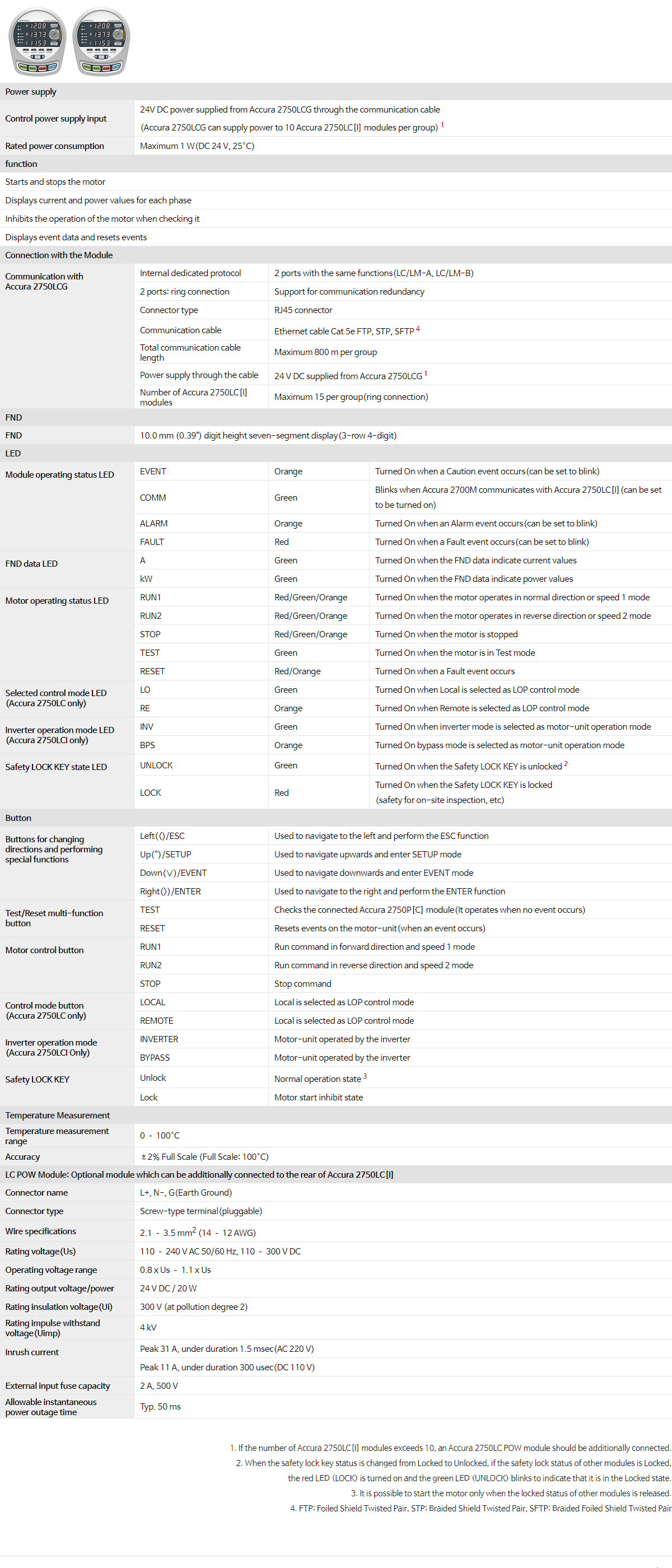
| Control power supply input | 24V DC power supplied from Accura 2750LCG through the communication cable (Accura 2750LCG can supply power to 10 Accura 2750LC[I] modules per group)1 |
||
| Rated power consumption | Maximum 1 W(DC 24 V, 25°C) | ||
| function | |||
| Starts and stops the motor | |||
| Displays current and power values for each phase | |||
| Inhibits the operation of the motor when checking it | |||
| Displays event data and resets events | |||
| Connection with the Module | |||
|
Communication with
Accura 2750LCG |
Internal dedicated protocol | 2 ports with the same functions(LC/LM-A, LC/LM-B) | |
| 2 ports: ring connection | Support for communication redundancy | ||
| Connector type | RJ45 connector | ||
| Communication cable | Ethernet cable Cat 5e FTP, STP, SFTP4 | ||
| Total communication cable length | Maximum 800 m per group | ||
| Power supply through the cable | 24 V DC supplied from Accura 2750LCG1 | ||
| Number of Accura 2750LC[I] modules | Maximum 15 per group(ring connection) | ||
| FND | |||
| FND | 10.0 mm (0.39") digit height seven-segment display(3-row 4-digit) | ||
| LED | |||
|
Module operating status LED
|
EVENT | Orange | Turned On when a Caution event occurs(can be set to blink) |
| COMM | Green | Blinks when Accura 2700M communicates with Accura 2750LC[I](can be set to be turned on) | |
| ALARM | Orange | Turned On when an Alarm event occurs(can be set to blink) | |
| FAULT | Red | Turned On when a Fault event occurs(can be set to blink) | |
|
FND data LED
|
A | Green | Turned On when the FND data indicate current values |
| kW | Green | Turned On when the FND data indicate power values | |
|
Motor operating status LED
|
RUN1 | Red/Green/Orange | Turned On when the motor operates in normal direction or speed 1 mode |
| RUN2 | Red/Green/Orange | Turned On when the motor operates in reverse direction or speed 2 mode | |
| STOP | Red/Green/Orange | Turned On when the motor is stopped | |
| TEST | Green | Turned On when the motor is in Test mode | |
| RESET | Red/Orange | Turned On when a Fault event occurs | |
|
Selected control mode LED
(Accura 2750LC only) |
LO | Green | Turned On when Local is selected as LOP control mode |
| RE | Orange | Turned On when Remote is selected as LOP control mode | |
|
Inverter operation mode LED
(Accura 2750LCI only) |
INV | Green | Turned On when inverter mode is selected as motor-unit operation mode |
| BPS | Orange | Turned On bypass mode is selected as motor-unit operation mode | |
|
Safety LOCK KEY state LED
|
UNLOCK | Green | Turned On when the Safety LOCK KEY is unlocked2 |
| LOCK | Red | Turned On when the Safety LOCK KEY is locked (safety for on-site inspection, etc) |
|
| Button | |||
|
Buttons for changing
directions and performing special functions |
Left(<)/ESC | Used to navigate to the left and perform the ESC function | |
| Up(^)/SETUP | Used to navigate upwards and enter SETUP mode | ||
| Down(∨)/EVENT | Used to navigate downwards and enter EVENT mode | ||
| Right(>)/ENTER | Used to navigate to the right and perform the ENTER function | ||
|
Test/Reset multi-function
button |
TEST | Checks the connected Accura 2750P[C] module(It operates when no event occurs) | |
| RESET | Resets events on the motor-unit(when an event occurs) | ||
|
Motor control button
|
RUN1 | Run command in forward direction and speed 1 mode | |
| RUN2 | Run command in reverse direction and speed 2 mode | ||
| STOP | Stop command | ||
|
Control mode button
(Accura 2750LC only) |
LOCAL | Local is selected as LOP control mode | |
| REMOTE | Local is selected as LOP control mode | ||
|
Inverter operation mode
(Accura 2750LCI Only) |
INVERTER | Motor-unit operated by the inverter | |
| BYPASS | Motor-unit operated by the inverter | ||
|
Safety LOCK KEY
|
Unlock | Normal operation state3 | |
| Lock | Motor start inhibit state | ||
| Temperature Measurement | |||
| Temperature measurement range | 0 – 100°C | ||
| Accuracy | ±2% Full Scale (Full Scale: 100°C) | ||
| LC POW Module: Optional module which can be additionally connected to the rear of Accura 2750LC[I] | |||
| Connector name | L+, N-, G(Earth Ground) | ||
| Connector type | Screw-type terminal(pluggable) | ||
| Wire specifications | 2.1 – 3.5 mm2 (14 – 12 AWG) | ||
| Rating voltage(Us) | 110 – 240 V AC 50/60 Hz, 110 – 300 V DC | ||
| Operating voltage range | 0.8 x Us – 1.1 x Us | ||
| Rating output voltage/power | 24 V DC / 20 W | ||
| Rating insulation voltage(Ui) | 300 V (at pollution degree 2) | ||
| Rating impulse withstand voltage(Uimp) | 4 kV | ||
|
Inrush current |
Peak 31 A, under duration 1.5 msec(AC 220 V) | ||
| Peak 11 A, under duration 300 usec(DC 110 V) | |||
| External input fuse capacity | 2 A, 500 V | ||
| Allowable instantaneous power outage time |
Typ. 50 ms | ||
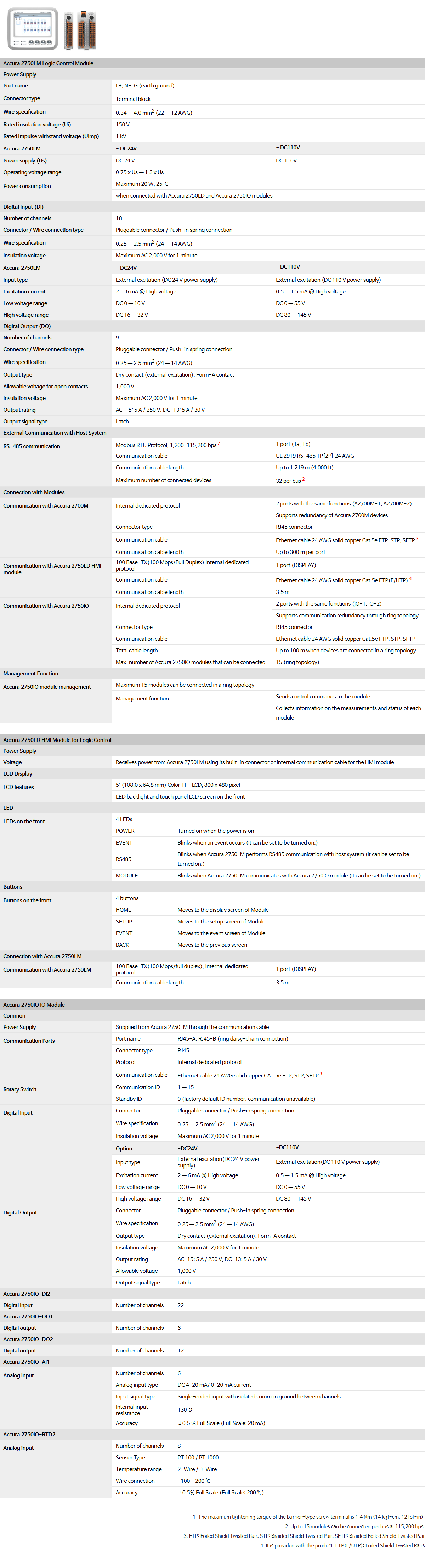
| Accura 2750LM Logic Control Module | ||||
| Power Supply | ||||
| Port name | L+, N-, G (earth ground) | |||
| Connector type | Terminal block1 | |||
| Wire specification | 0.34 — 4.0 mm2 (22 — 12 AWG) | |||
| Rated insulation voltage (Ui) | 150 V | |||
| Rated impulse withstand voltage (Uimp) | 1 kV | |||
| Accura 2750LM | - DC24V | - DC110V | ||
| Power supply (Us) | DC 24 V | DC 110V | ||
| Operating voltage range | 0.75 x Us — 1.3 x Us | |||
|
Power consumption
|
Maximum 20 W, 25°C | |||
| when connected with Accura 2750LD and Accura 2750IO modules | ||||
| Digital Input (DI) | ||||
| Number of channels | 18 | |||
| Connector / Wire connection type | Pluggable connector / Push-in spring connection | |||
| Wire specification | 0.25 — 2.5 mm2 (24 — 14 AWG) | |||
| Insulation voltage | Maximum AC 2,000 V for 1 minute | |||
| Accura 2750LM | - DC24V | - DC110V | ||
| Input type | External excitation (DC 24 V power supply) | External excitation (DC 110 V power supply) | ||
| Excitation current | 2 — 6 mA @ High voltage | 0.5 — 1.5 mA @ High voltage | ||
| Low voltage range | DC 0 — 10 V | DC 0 — 55 V | ||
| High voltage range | DC 16 — 32 V | DC 80 — 145 V | ||
| Digital Output (DO) | ||||
| Number of channels | 9 | |||
| Connector / Wire connection type | Pluggable connector / Push-in spring connection | |||
| Wire specification | 0.25 — 2.5 mm2 (24 — 14 AWG) | |||
| Output type | Dry contact (external excitation), Form-A contact | |||
| Allowable voltage for open contacts | 1,000 V | |||
| Insulation voltage | Maximum AC 2,000 V for 1 minute | |||
| Output rating | AC-15: 5 A / 250 V, DC-13: 5 A / 30 V | |||
| Output signal type | Latch | |||
| External Communication with Host System | ||||
|
RS-485 communication
|
Modbus RTU Protocol, 1,200-115,200 bps2 | 1 port (Ta, Tb) | ||
| Communication cable | UL 2919 RS-485 1P[2P] 24 AWG | |||
| Communication cable length | Up to 1,219 m (4,000 ft) | |||
| Maximum number of connected devices | 32 per bus2 | |||
| Connection with Modules | ||||
|
Communication with Accura 2700M
|
Internal dedicated protocol
|
2 ports with the same functions (A2700M-1, A2700M-2) | ||
| Supports redundancy of Accura 2700M devices | ||||
| Connector type | RJ45 connector | |||
| Communication cable | Ethernet cable 24 AWG solid copper Cat 5e FTP, STP, SFTP3 | |||
| Communication cable length | Up to 300 m per port | |||
|
Communication with Accura 2750LD HMI module
|
100 Base-TX(100 Mbps/Full Duplex) Internal dedicated protocol | 1 port (DISPLAY) | ||
| Communication cable | Ethernet cable 24 AWG solid copper Cat.5e FTP(F/UTP)4 | |||
| Communication cable length | 3.5 m | |||
|
Communication with
Accura 2750IO
|
Internal dedicated protocol
|
2 ports with the same functions (IO-1, IO-2) | ||
| Supports communication redundancy through ring topology | ||||
| Connector type | RJ45 connector | |||
| Communication cable | Ethernet cable 24 AWG solid copper Cat.5e FTP, STP, SFTP | |||
| Total cable length | Up to 100 m when devices are connected in a ring topology | |||
| Max. number of Accura 2750IO modules that can be connected | 15 (ring topology) | |||
| Management Function | ||||
|
Accura 2750IO
module management
|
Maximum 15 modules can be connected in a ring topology | |||
|
Management function
|
Sends control commands to the module | |||
| Collects information on the measurements and status of each module | ||||
| Accura 2750LD HMI Module for Logic Control | ||||
| Power Supply | ||||
| Voltage | Receives power from Accura 2750LM using its built-in connector or internal communication cable for the HMI module | |||
| LCD Display | ||||
|
LCD features
|
5" (108.0 x 64.8 mm) Color TFT LCD, 800 x 480 pixel | |||
| LED backlight and touch panel LCD screen on the front | ||||
| LED | ||||
|
LEDs on the front
|
4 LEDs | |||
| POWER | Turned on when the power is on | |||
| EVENT | Blinks when an event occurs (It can be set to be turned on.) | |||
| RS485 | Blinks when Accura 2750LM performs RS485 communication with host system (It can be set to be turned on.) | |||
| MODULE | Blinks when Accura 2750LM communicates with Accura 2750IO module (It can be set to be turned on.) | |||
| Buttons | ||||
|
Buttons on the front
|
4 buttons | |||
| HOME | Moves to the display screen of Module | |||
| SETUP | Moves to the setup screen of Module | |||
| EVENT | Moves to the event screen of Module | |||
| BACK | Moves to the previous screen | |||
| Connection with Accura 2750LM | ||||
|
Communication with
Accura 2750LM
|
100 Base-TX(100 Mbps/full duplex), Internal dedicated protocol | 1 port (DISPLAY) | ||
| Communication cable length | 3.5 m | |||
| Accura 2750IO IO Module | ||||
| Common | ||||
| Power Supply | Supplied from Accura 2750LM through the communication cable | |||
|
Communication Ports
|
Port name | RJ45-A, RJ45-B (ring daisy-chain connection) | ||
| Connector type | RJ45 | |||
| Protocol | Internal dedicated protocol | |||
| Communication cable | Ethernet cable 24 AWG solid copper CAT.5e FTP, STP, SFTP3 | |||
|
Rotary Switch
|
Communication ID | 1 — 15 | ||
| Standby ID | 0 (factory default ID number, communication unavailable) | |||
|
Digital Input
|
Connector | Pluggable connector / Push-in spring connection | ||
| Wire specification | 0.25 — 2.5 mm2 (24 — 14 AWG) | |||
| Insulation voltage | Maximum AC 2,000 V for 1 minute | |||
| Option | -DC24V | -DC110V | ||
| Input type | External excitation(DC 24 V power supply) | External excitation(DC 110 V power supply) | ||
| Excitation current | 2 — 6 mA @ High voltage | 0.5 — 1.5 mA @ High voltage | ||
| Low voltage range | DC 0 — 10 V | DC 0 — 55 V | ||
| High voltage range | DC 16 — 32 V | DC 80 — 145 V | ||
|
Digital Output
|
Connector | Pluggable connector / Push-in spring connection | ||
| Wire specification | 0.25 — 2.5 mm2 (24 — 14 AWG) | |||
| Output type | Dry contact (external excitation), Form-A contact | |||
| Insulation voltage | Maximum AC 2,000 V for 1 minute | |||
| Output rating | AC-15: 5 A / 250 V, DC-13: 5 A / 30 V | |||
| Allowable voltage | 1,000 V | |||
| Output signal type | Latch | |||
| Accura 2750IO-DI2 | ||||
| Digital input | Number of channels | 22 | ||
| Accura 2750IO-DO1 | ||||
| Digital output | Number of channels | 6 | ||
| Accura 2750IO-DO2 | ||||
| Digital output | Number of channels | 12 | ||
| Accura 2750IO-AI1 | ||||
|
Analog input
|
Number of channels | 6 | ||
| Analog input type | DC 4-20 mA/ 0-20 mA current | |||
| Input signal type | Single-ended input with isolated common ground between channels | |||
| Internal input resistance | 130 Ω | |||
| Accuracy | ±0.5 % Full Scale (Full Scale: 20 mA) | |||
| Accura 2750IO-RTD2 | ||||
|
Analog input
|
Number of channels | 8 | ||
| Sensor Type | PT 100 / PT 1000 | |||
| Temperature range | 2-Wire / 3-Wire | |||
| Wire connection | -100 - 200 ℃ | |||
| Accuracy | ±0.5% Full Scale (Full Scale: 200 ℃) | |||
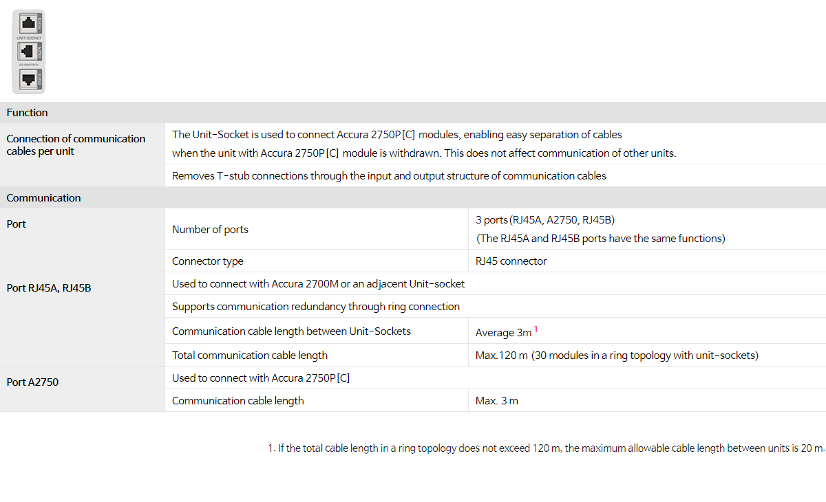
| Function | |||
|
Connection of communication cables per unit |
The Unit-Socket is used to connect Accura 2750P[C] modules, enabling easy separation of cables when the unit with Accura 2750P[C] module is withdrawn. This does not affect communication of other units. |
||
| Removes T-stub connections through the input and output structure of communication cables | |||
| Communication | |||
|
Port |
Number of ports |
3 ports(RJ45A, A2750, RJ45B) (The RJ45A and RJ45B ports have the same functions) |
|
| Connector type | RJ45 connector | ||
|
RJ45A, RJ45B Port |
Used to connect with Accura 2700M or an adjacent Unit-socket | ||
| Supports communication redundancy through ring connection | |||
| Communication cable length between Unit-Sockets | Average 3m1 | ||
| Total communication cable length | Max.120 m (30 modules in a ring topology with unit-sockets) | ||
|
Accura 2750 Port |
Used to connect with Accura 2750P[C] | ||
| Communication cable length | Max. 3 m | ||
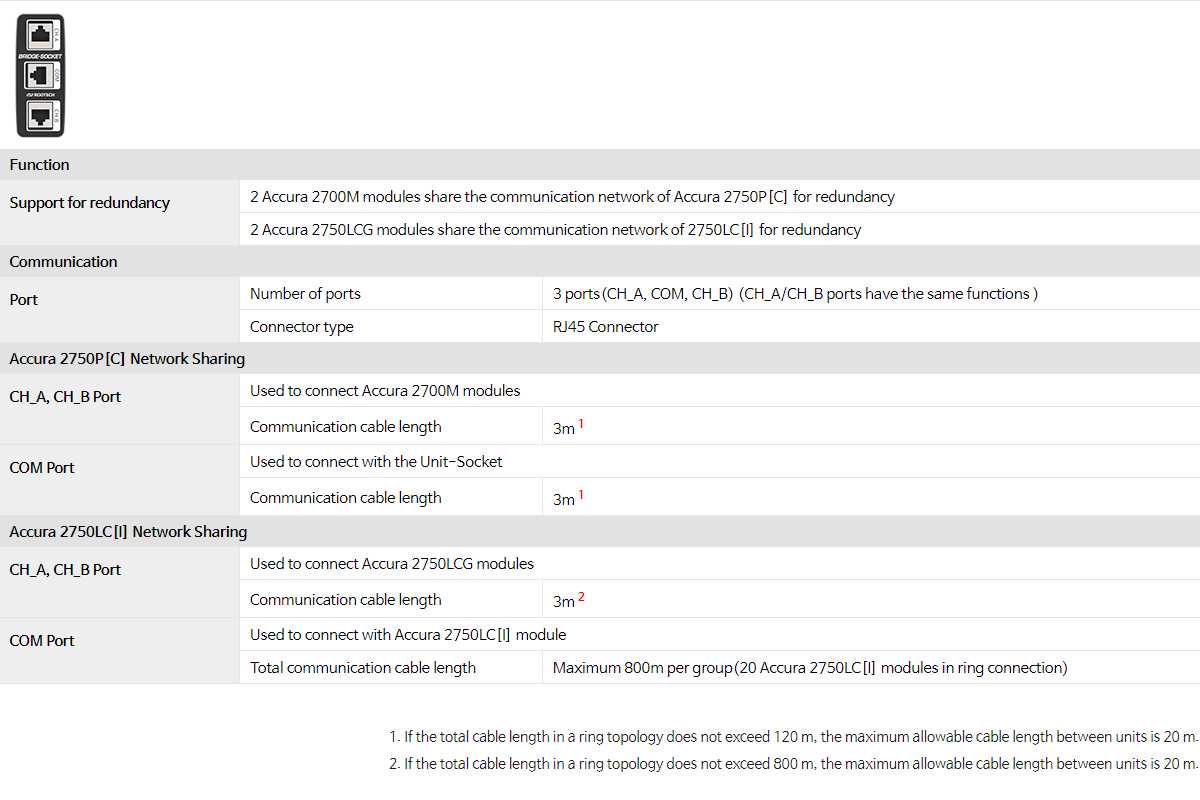
| Function | |||
|
Support for redundancy |
2 Accura 2700M modules share the communication network of Accura 2750P[C] for redundancy | ||
| 2 Accura 2750LCG modules share the communication network of 2750LC[I] for redundancy | |||
| Communication | |||
|
Port |
Number of ports | 3 ports(CH_A, COM, CH_B) (CH_A/CH_B ports have the same functions ) | |
| Connector type | RJ45 Connector | ||
| Accura 2750P[C] Network Sharing | |||
|
CH_A, CH_B Port |
Used to connect Accura 2700M modules | ||
| Communication cable length | 3m1 | ||
|
COM Port |
Used to connect with the Unit-Socket | ||
| Communication cable length | 3m1 | ||
| Accura 2750LC[I] Network Sharing | |||
|
CH_A, CH_B Port |
Used to connect Accura 2750LCG modules | ||
| Communication cable length | 3m2 | ||
|
COM Port |
Used to connect with Accura 2750LC[I] module | ||
| Total communication cable length | Max. 800 m per group (15 Accura 2750LC[I] modules in a ring connection) | ||
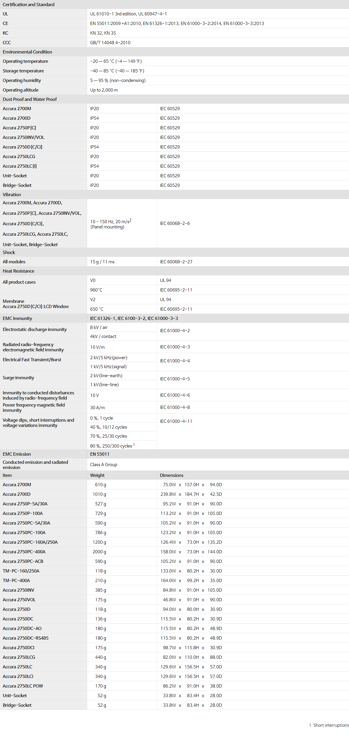
| Certification and Standard | |||
| UL | UL 61010-1 3rd edition, UL 60947-4-1 | ||
| CE | EN 55011:2009 +A1:2010, EN 61326-1:2013, EN 61000-3-2:2014, EN 61000-3-3:2013 | ||
| KC | KN 32, KN 35 | ||
| CCC | GB/T 14048.4-2010 | ||
| Environmental Condition | |||
| Operating temperature | -20 — 65 °C (-4 — 149 ℉) | ||
| Storage temperature | -40 — 85 °C (-40 — 185 ℉) | ||
| Operating humidity | 5 — 95 % (non-condensing) | ||
| Operating altitude | Up to 2,000 m | ||
| Dust Proof and Water Proof | |||
| Accura 2700M | IP20 | IEC 60529 | |
| Accura 2700D | IP54 | IEC 60529 | |
| Accura 2750P[C] | IP20 | IEC 60529 | |
| Accura 2750INV/VOL | IP20 | IEC 60529 | |
| Accura 2750D[C/CI] | IP54 | IEC 60529 | |
| Accura 2750LCG | IP20 | IEC 60529 | |
| Accura 2750LC[I] | IP54 | IEC 60529 | |
| Accura 2750LM | IP20 | IEC 60529 | |
| Accura 2750LD | IP54 | IEC 60529 | |
| Accura 2750IO-DI2/DO1/DO2/AI1/RTD2 | IP20 | IEC 60529 | |
| Unit-Socket | IP20 | IEC 60529 | |
| Bridge-Socket | IP20 | IEC 60529 | |
| Vibration | |||
|
Accura 2700M, Accura 2700D, Accura 2750P[C], Accura 2750INV/VOL, Accura 2750D[C/CI], Accura 2750LCG, Accura 2750LC, Unit-Socket, Bridge-Socket |
10 - 150 Hz, 20 m/s2 (Panel mounting) |
IEC 60068-2-6 | |
| Shock | |||
| All modules | 15 g / 11 ms | IEC 60068-2-27 | |
| Heat Resistance | |||
|
All product cases |
V0 | UL 94 | |
| 960°C | IEC 60695-2-11 | ||
|
Membrane Accura 2750D[C/CI] LCD Window |
V2 | UL 94 | |
| 650 °C | IEC 60695-2-11 | ||
| EMC Immunity | IEC 61326-1, IEC 6100-3-2, IEC 61000-3-3 | ||
|
Electrostatic discharge immunity |
8 kV / air |
IEC 61000-4-2 |
|
| 4kV / contact | |||
| Radiated radio-frequency electromagnetic field immunity | 10 V/m | IEC 61000-4-3 | |
|
Electrical Fast Transient/Burst |
2 kV/5 kHz(power) |
IEC 61000-4-4 |
|
| 1 kV/5 kHz(signal) | |||
|
Surge immunity |
2 kV(line-earth) |
IEC 61000-4-5 |
|
| 1 kV(line-line) | |||
| Immunity to conducted disturbances induced by radio-frequency field | 10 V | IEC 61000-4-6 | |
| Power frequency magnetic field immunity | 30 A/m | IEC 61000-4-8 | |
|
Voltage dips, short interruptions and voltage variations immunity |
0 %, 1 cycle |
IEC 61000-4-11 |
|
| 40 %, 10/12 cycles | |||
| 70 %, 25/30 cycles | |||
| 80 %, 250/300 cycles1 | |||
| EMC Emission | EN 55011 | ||
| Conducted emission and radiated emission | Class A Group | ||
| Item | Weight | Dimensions | |
| Accura 2700M |
610 g
|
75.0W
x
157.0H
x
94.0D
|
|
| Accura 2700D |
1010 g
|
239.8W
x
184.7H
x
42.5D
|
|
| Accura 2750P-5A/30A |
527 g
|
95.2W
x
91.0H
x
90.0D
|
|
| Accura 2750P-100A |
729 g
|
113.2W
x
91.0H
x
105.0D
|
|
| Accura 2750PC-5A/30A |
590 g
|
105.2W
x
91.0H
x
90.0D
|
|
| Accura 2750PC-100A |
786 g
|
123.2W
x
91.0H
x
105.0D
|
|
| Accura 2750PC-160A/250A |
1200 g
|
126.4W
x
73.0H
x
135.2D
|
|
| Accura 2750PC-400A |
2000 g
|
158.0W
x
73.0H
x
144.0D
|
|
| Accura 2750PC-ACB |
590 g
|
105.2W
x
91.0H
x
90.0D
|
|
| TM-PC-160/250A |
118 g
|
133.0W
x
80.2H
x
30.0D
|
|
| TM-PC-400A |
210 g
|
164.0W
x
99.2H
x
35.0D
|
|
| Accura 2750INV |
385 g
|
84.8W
x
91.0H
x
105.0D
|
|
| Accura 2750VOL |
175 g
|
46.8W
x
91.0H
x
90.0D
|
|
| Accura 2750D |
118 g
|
94.0W
x
80.0H
x
30.9D
|
|
| Accura 2750DC |
136 g
|
115.5W
x
80.2H
x
30.9D
|
|
| Accura 2750DC-AO |
180 g
|
115.5W
x
80.2H
x
48.9D
|
|
| Accura 2750DC-RS485 |
180 g
|
115.5W
x
80.2H
x
48.9D
|
|
| Accura 2750DCI |
175 g
|
98.7W
x
115.8H
x
30.9D
|
|
| Accura 2750LCG |
440 g
|
82.0W
x
110.0H
x
88.0D
|
|
| Accura 2750LC |
340 g
|
129.6W
x
156.5H
x
57.0D
|
|
| Accura 2750LCI |
340 g
|
129.6W
x
156.5H
x
57.0D
|
|
| Accura 2750LC POW |
170 g
|
86.2W
x
91.0H
x
38.0D
|
|
| Accura 2750LM |
148.6W
x
126.6H
x
77.2D
|
550 g
|
|
| Accura 2750LD |
151.5W
x
129.6H
x
33.0D
|
400 g
|
|
| Accura 2750IO-DO1/AI1 |
25.0W
x
103.0H
x
114.5D
|
200 g
|
|
| Accura 2750IO-DI2/DO2/RTD2 |
48.0W
x
103.0H
x
114.5D
|
280 g
|
|
| Unit-Socket |
52 g
|
33.8W
x
83.4H
x
28.0D
|
|
| Bridge-Socket |
52 g
|
33.8W
x
83.4H
x
28.0D
|
|


|
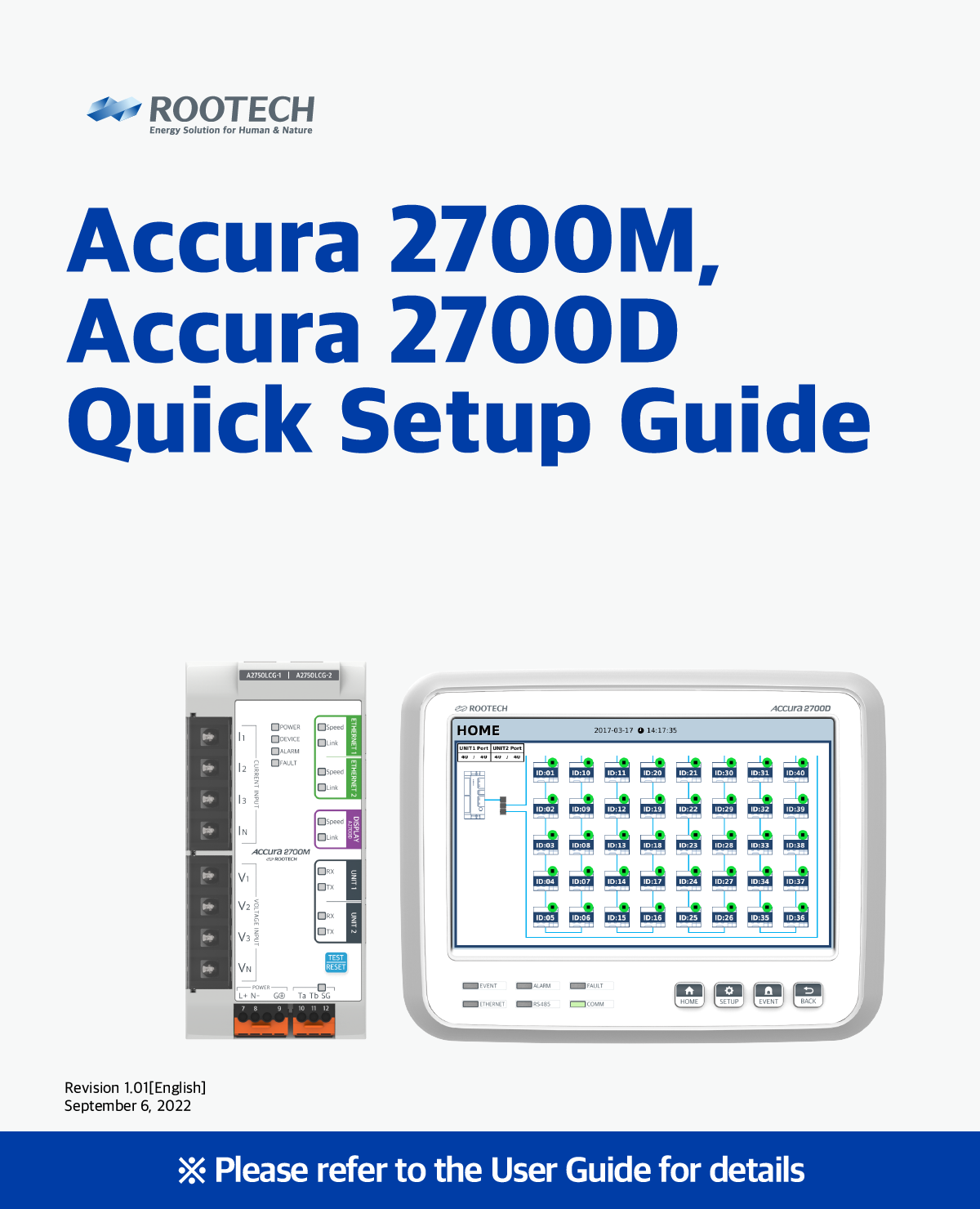
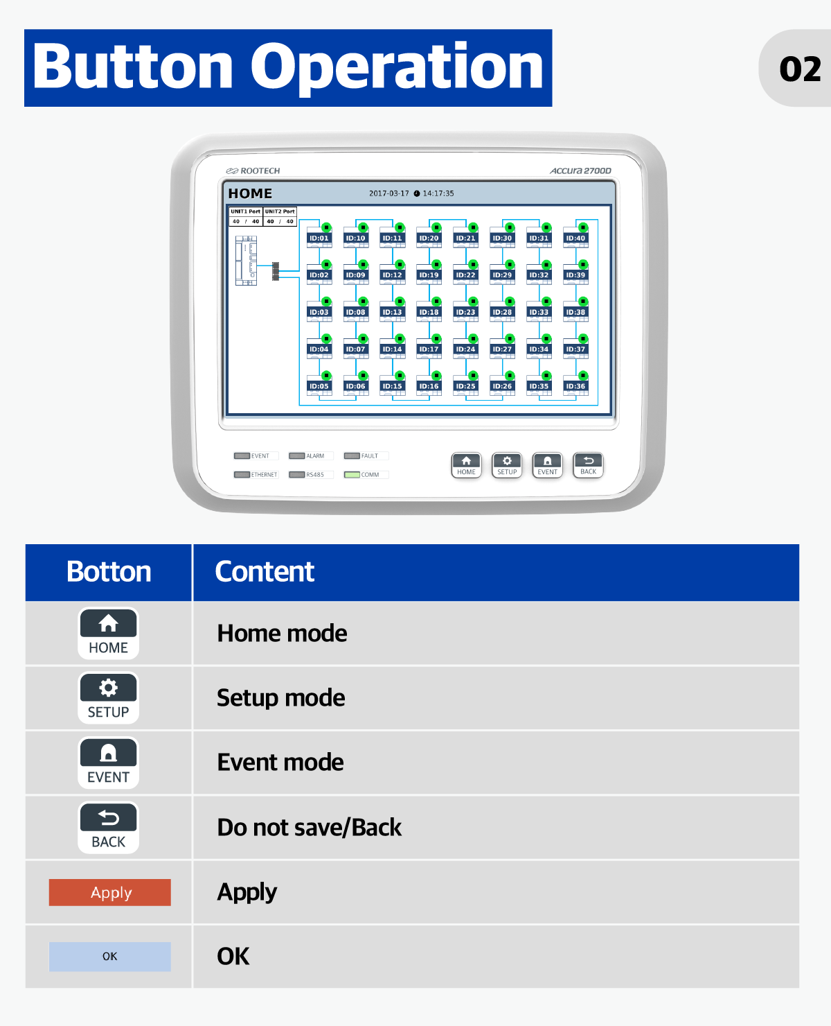
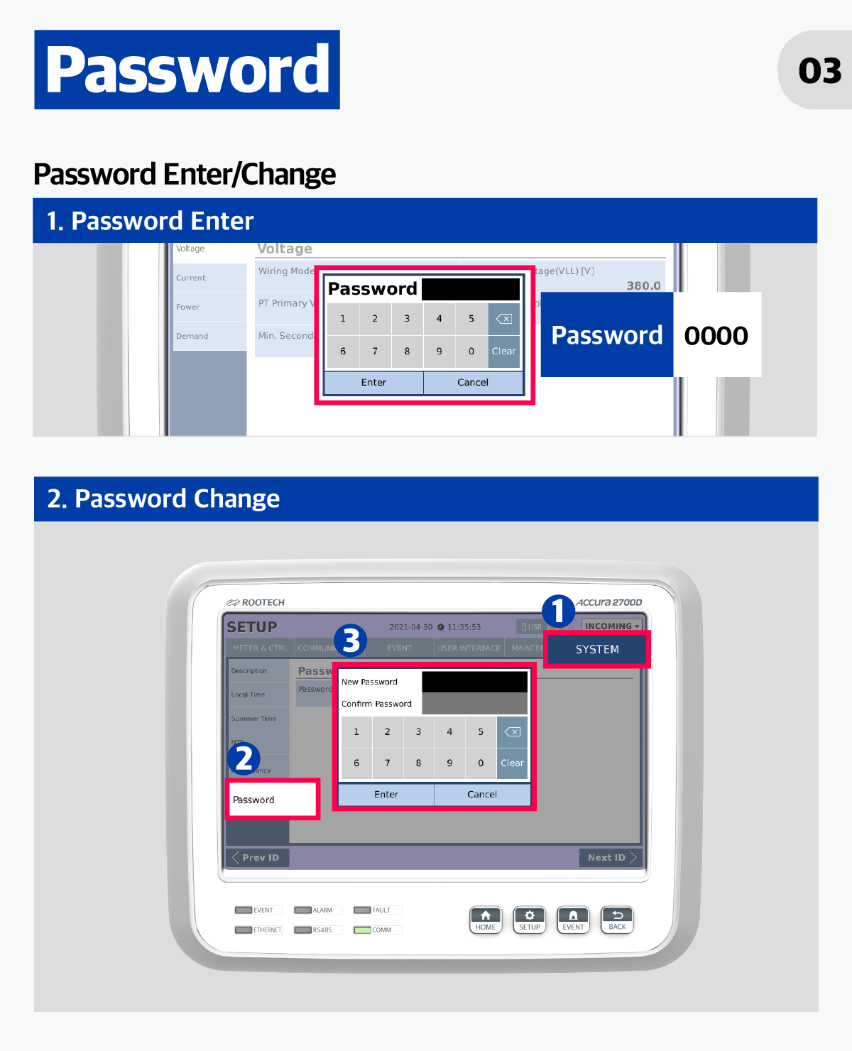
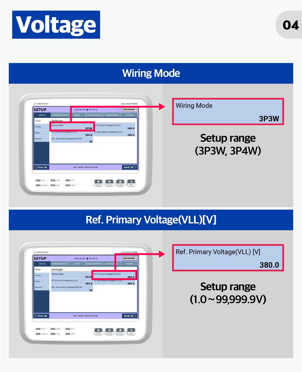
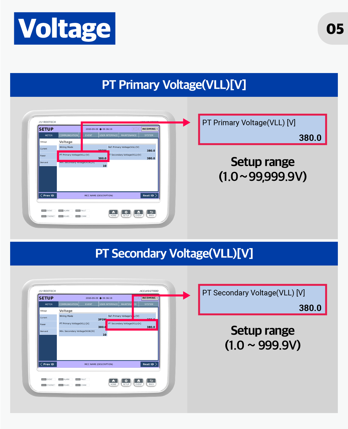
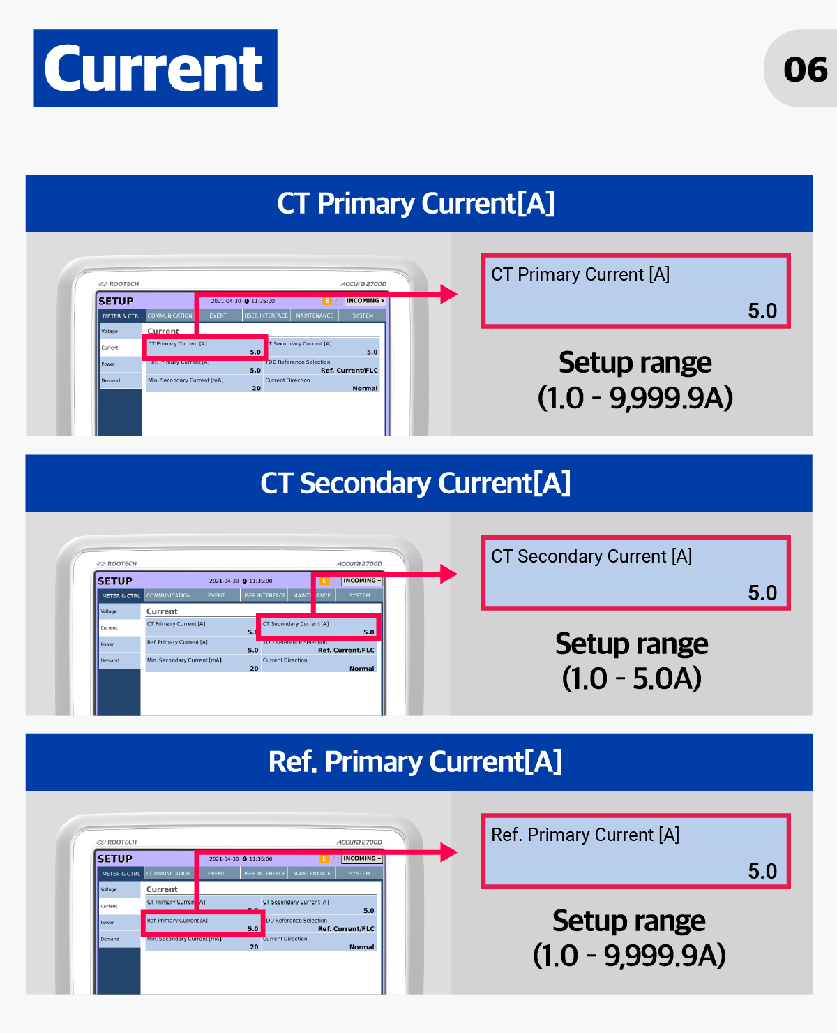
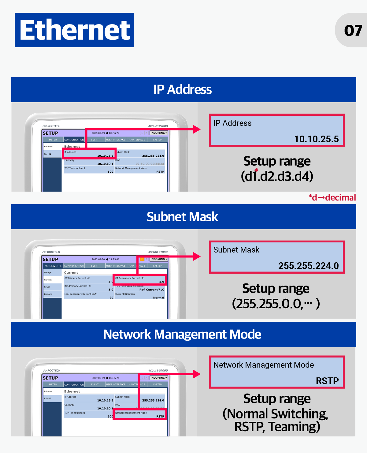


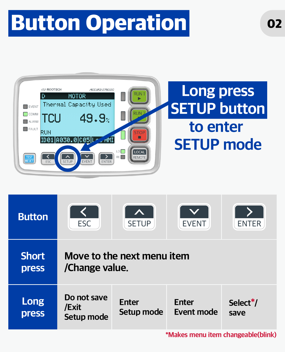
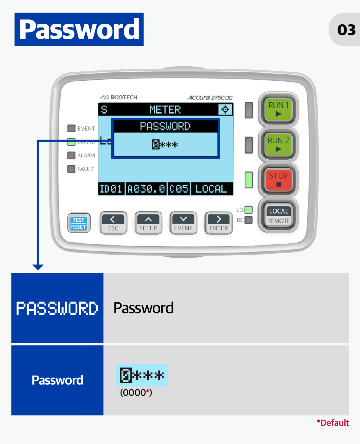
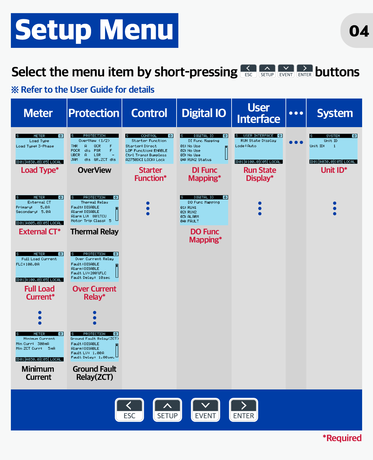
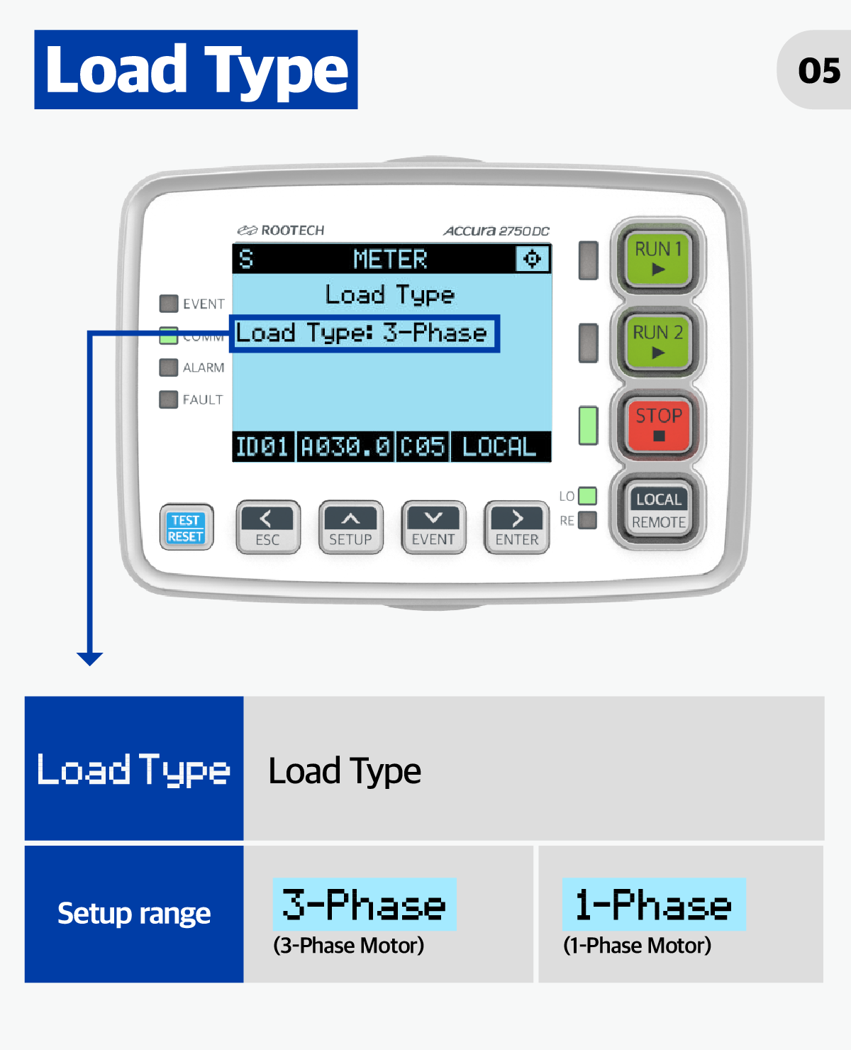
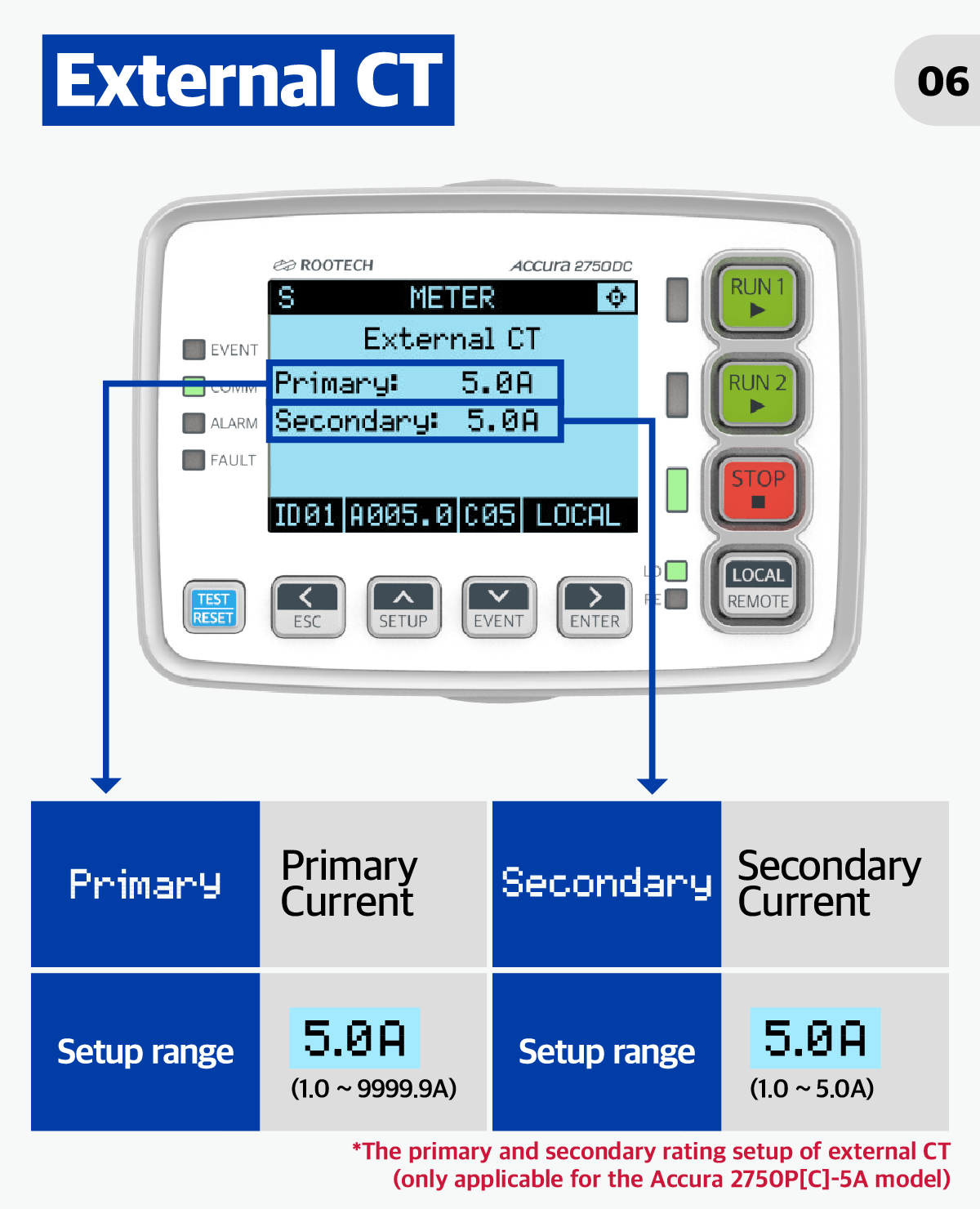
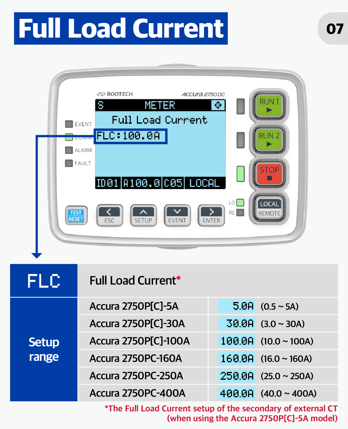
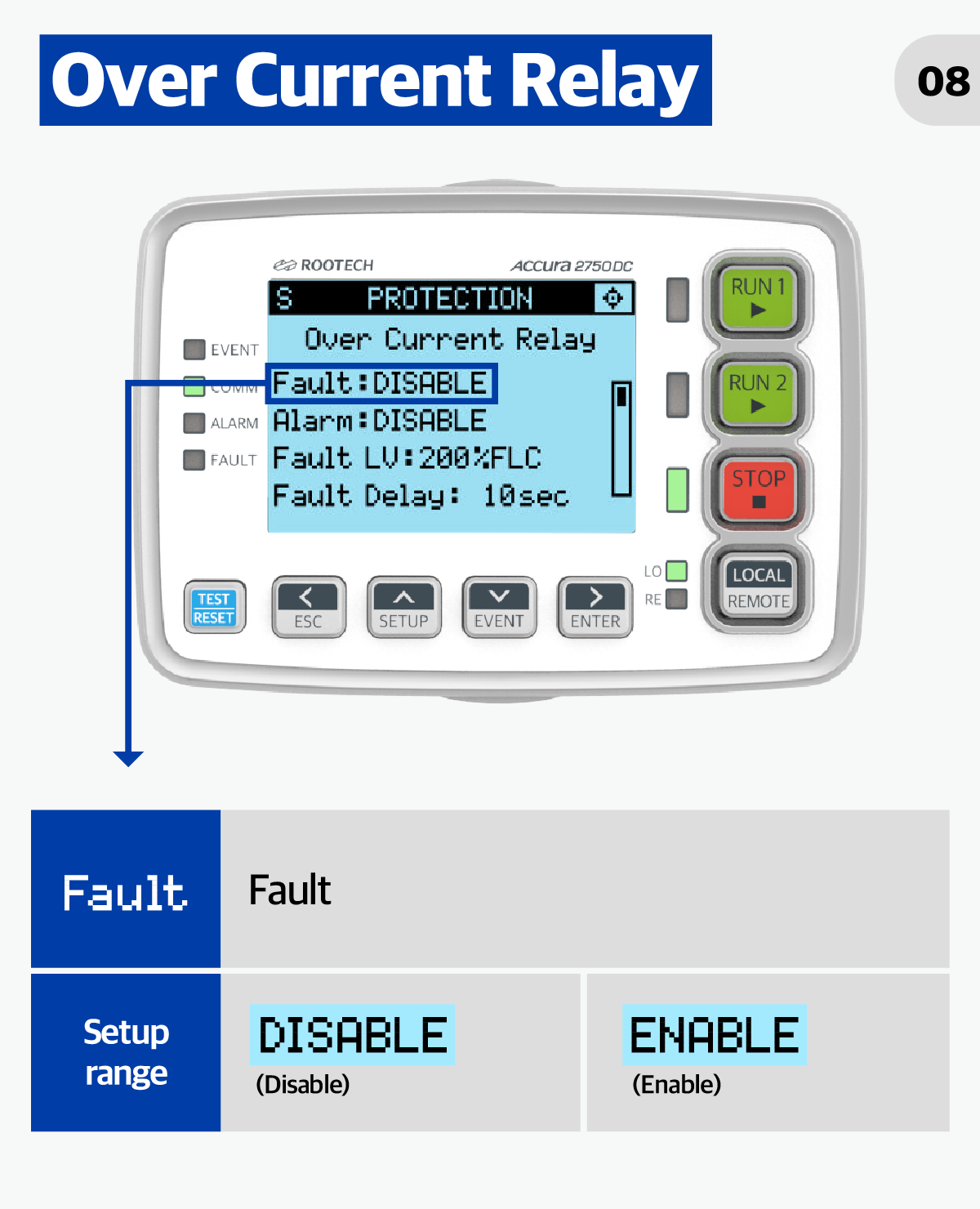
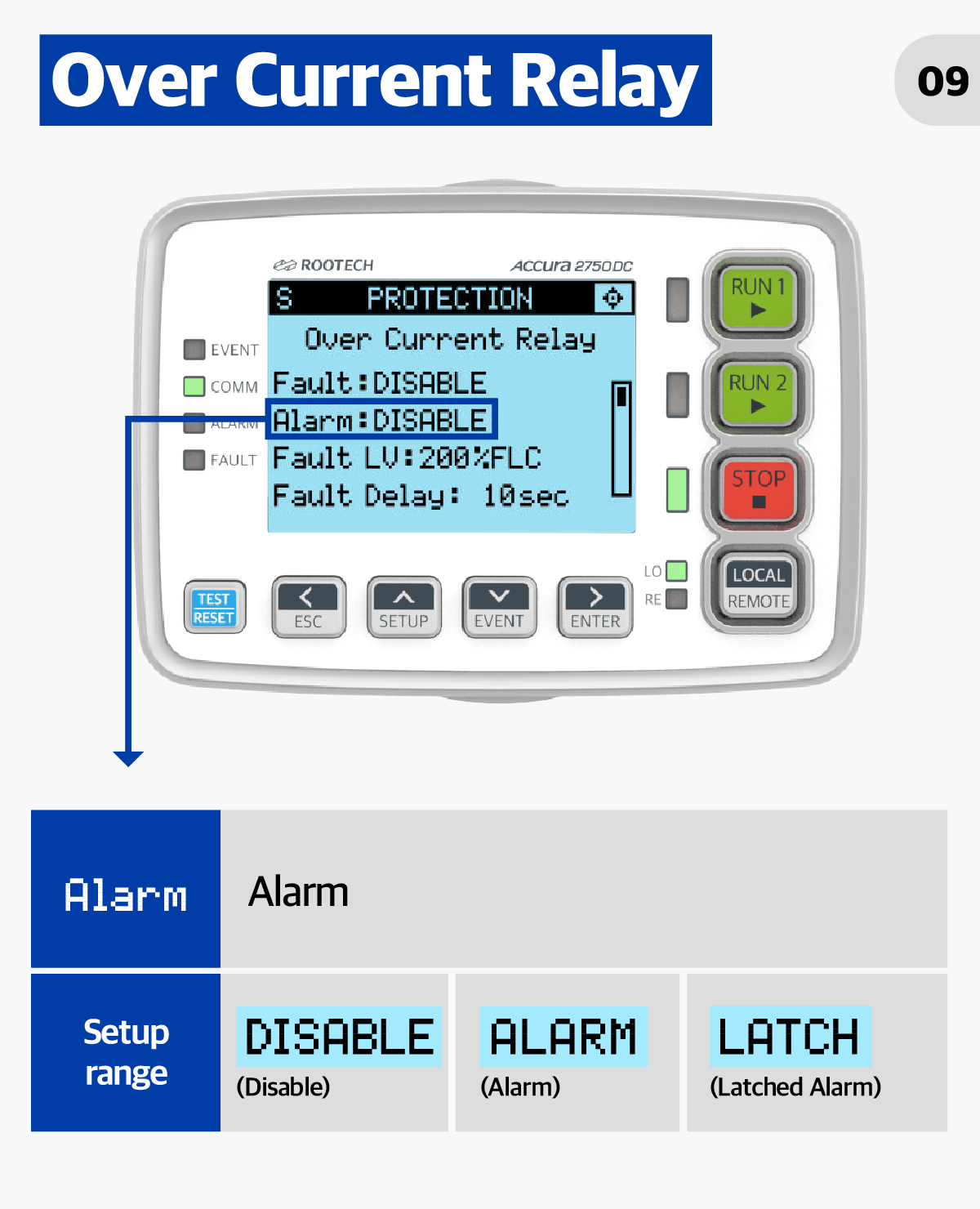
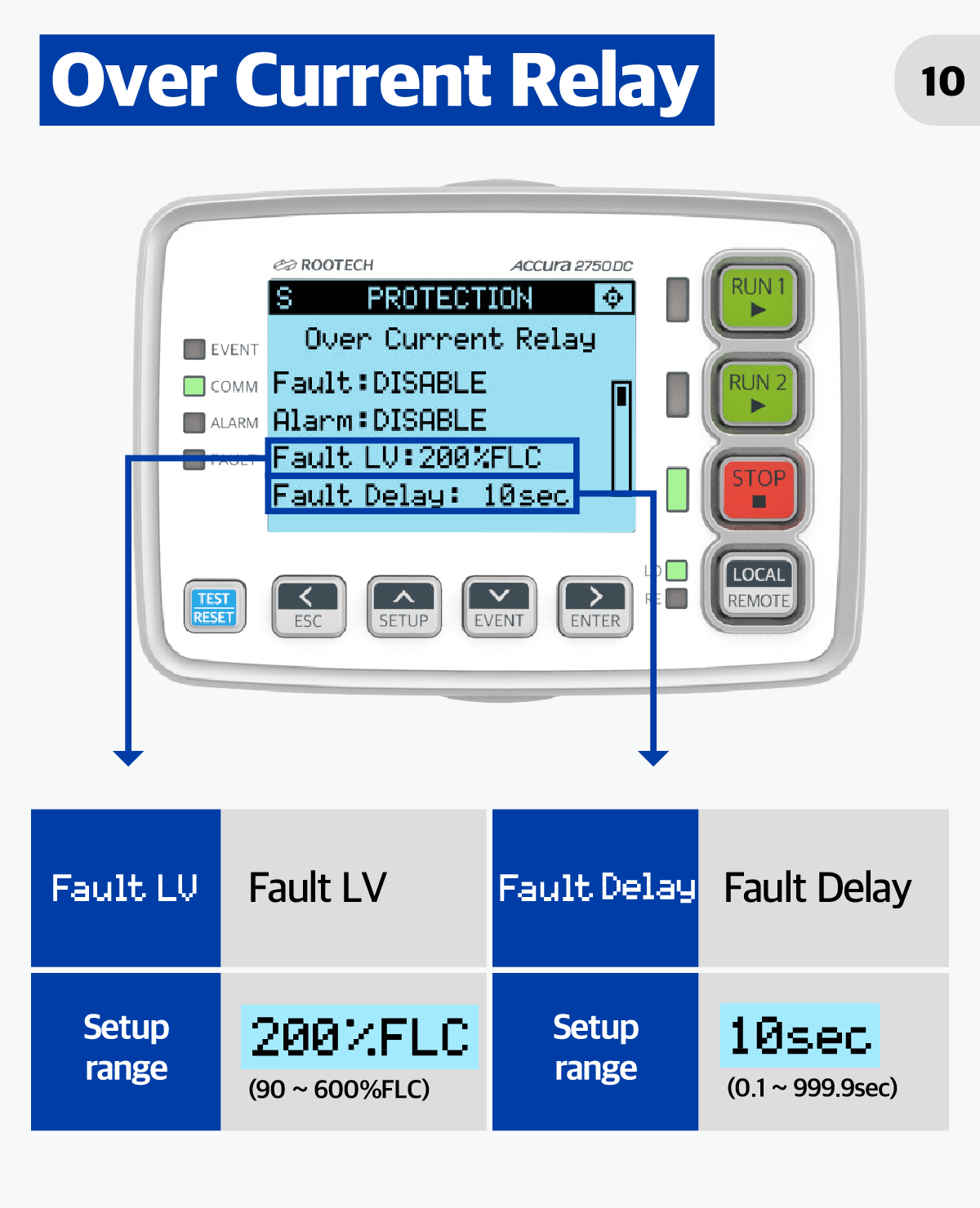
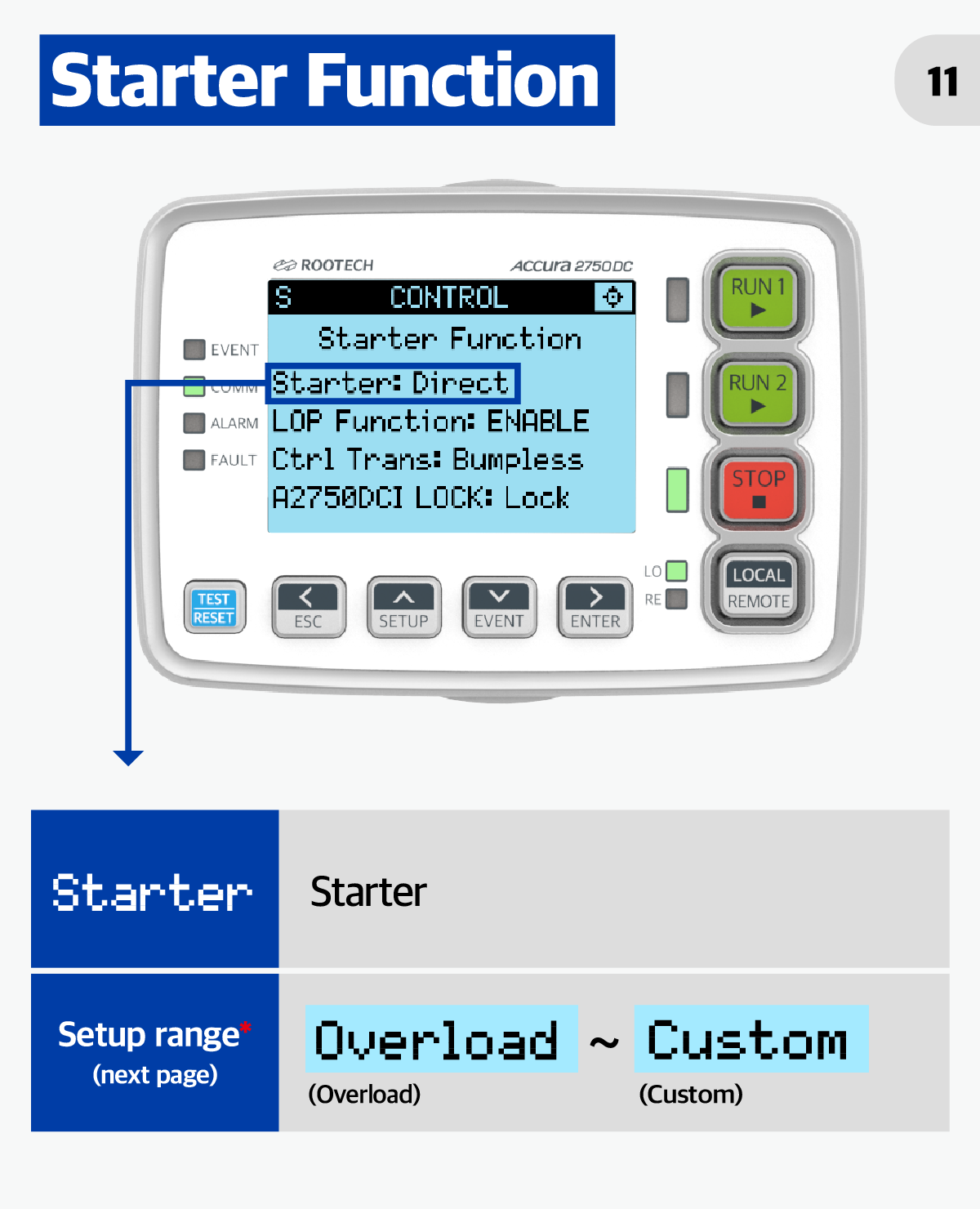
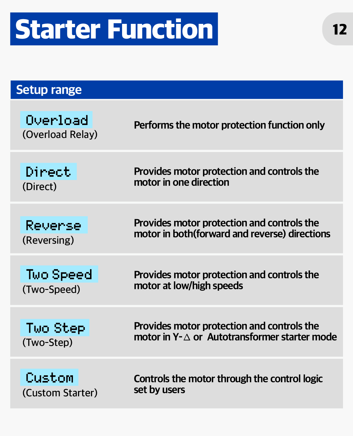
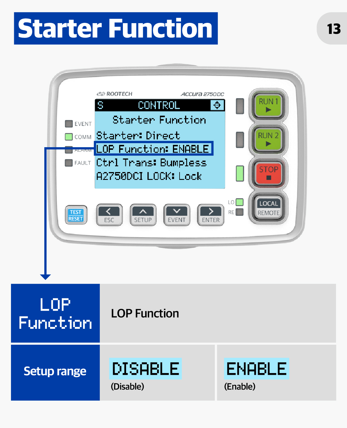
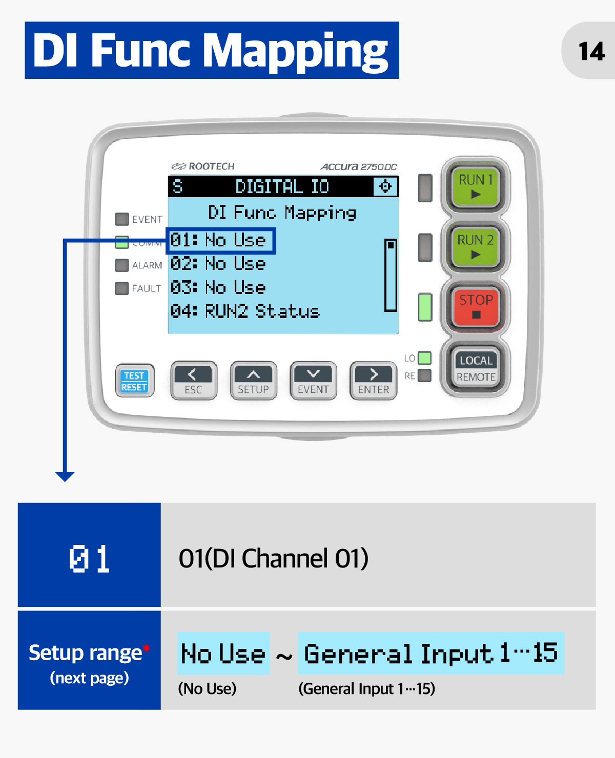
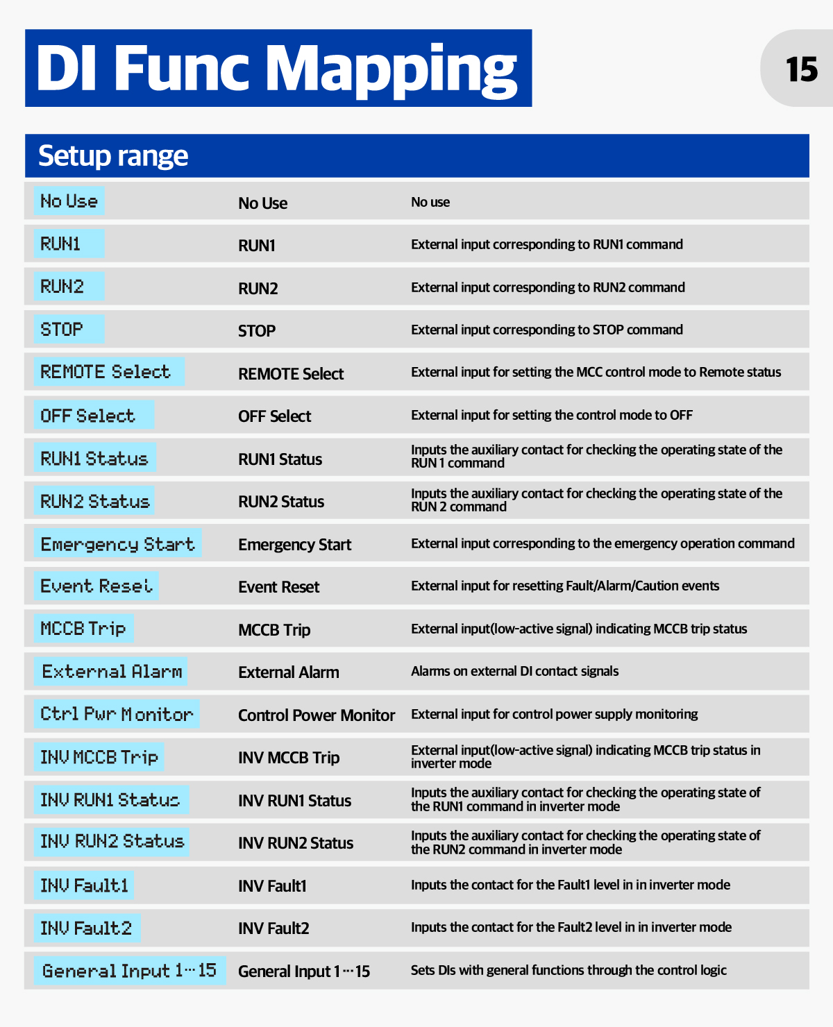
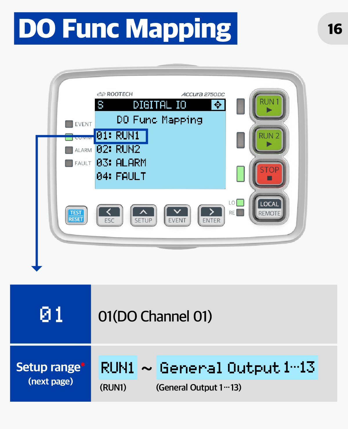
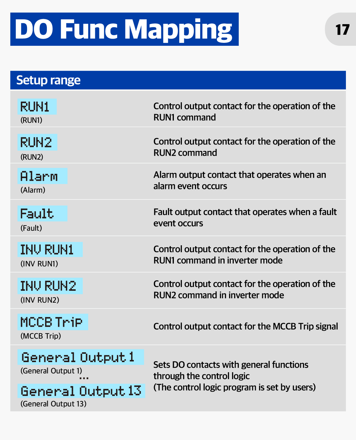
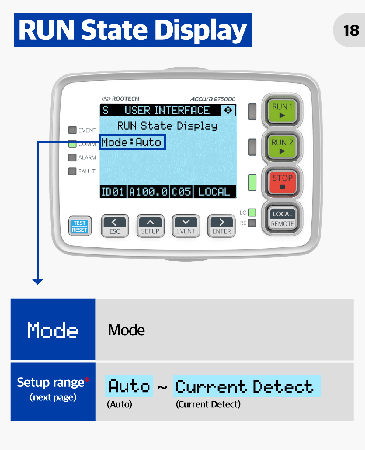
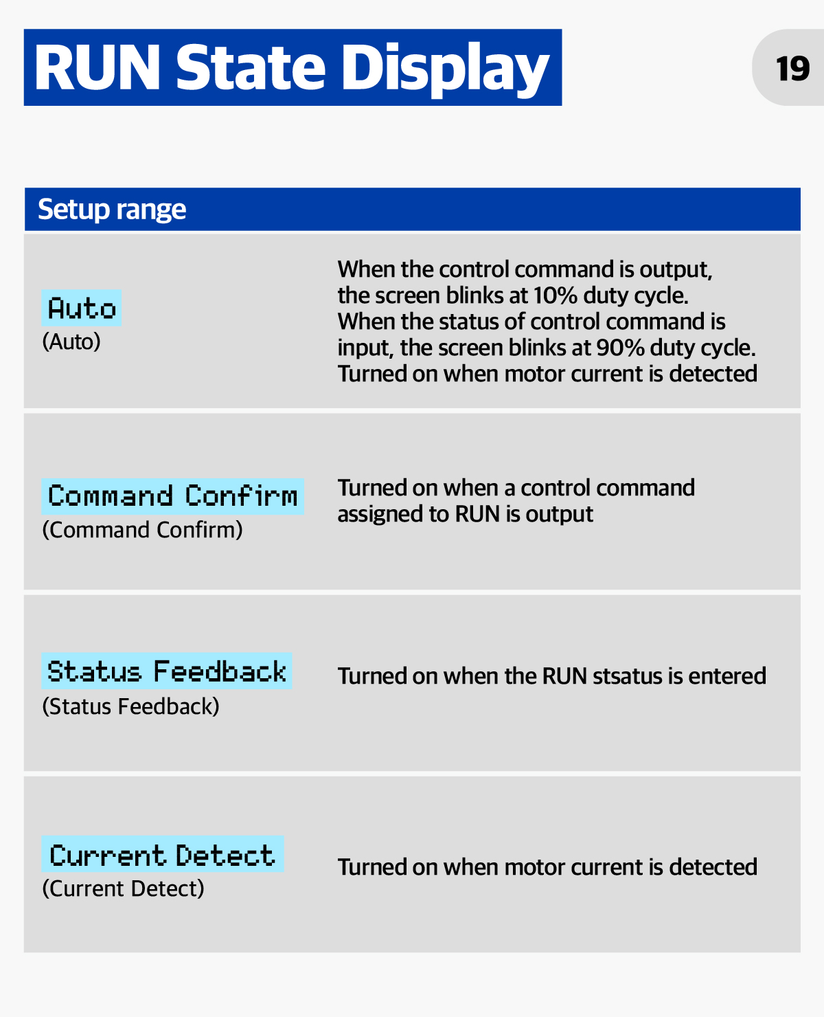
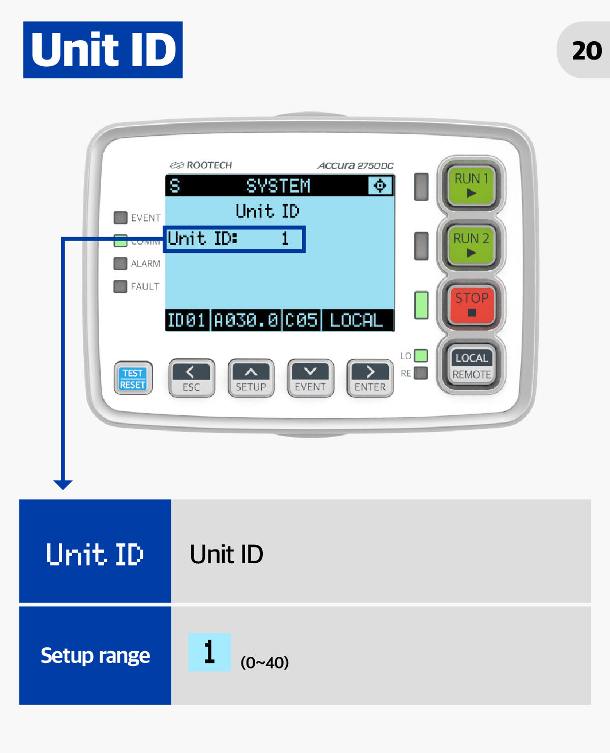
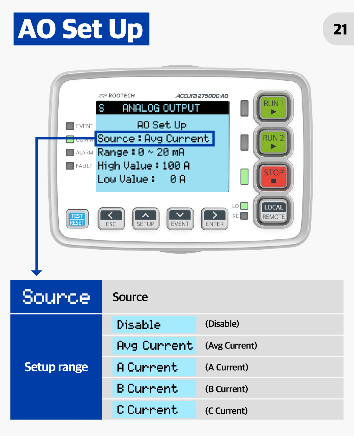
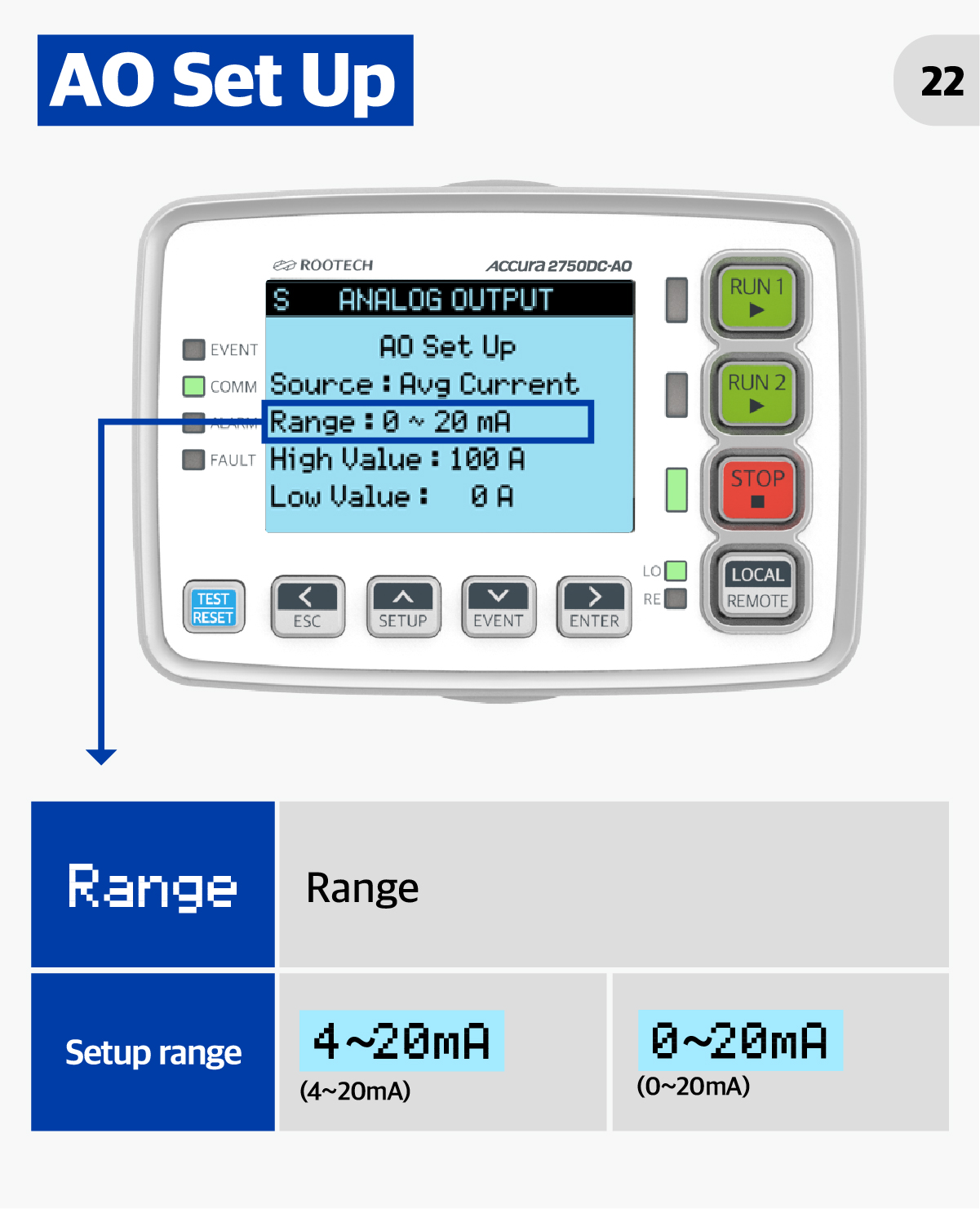
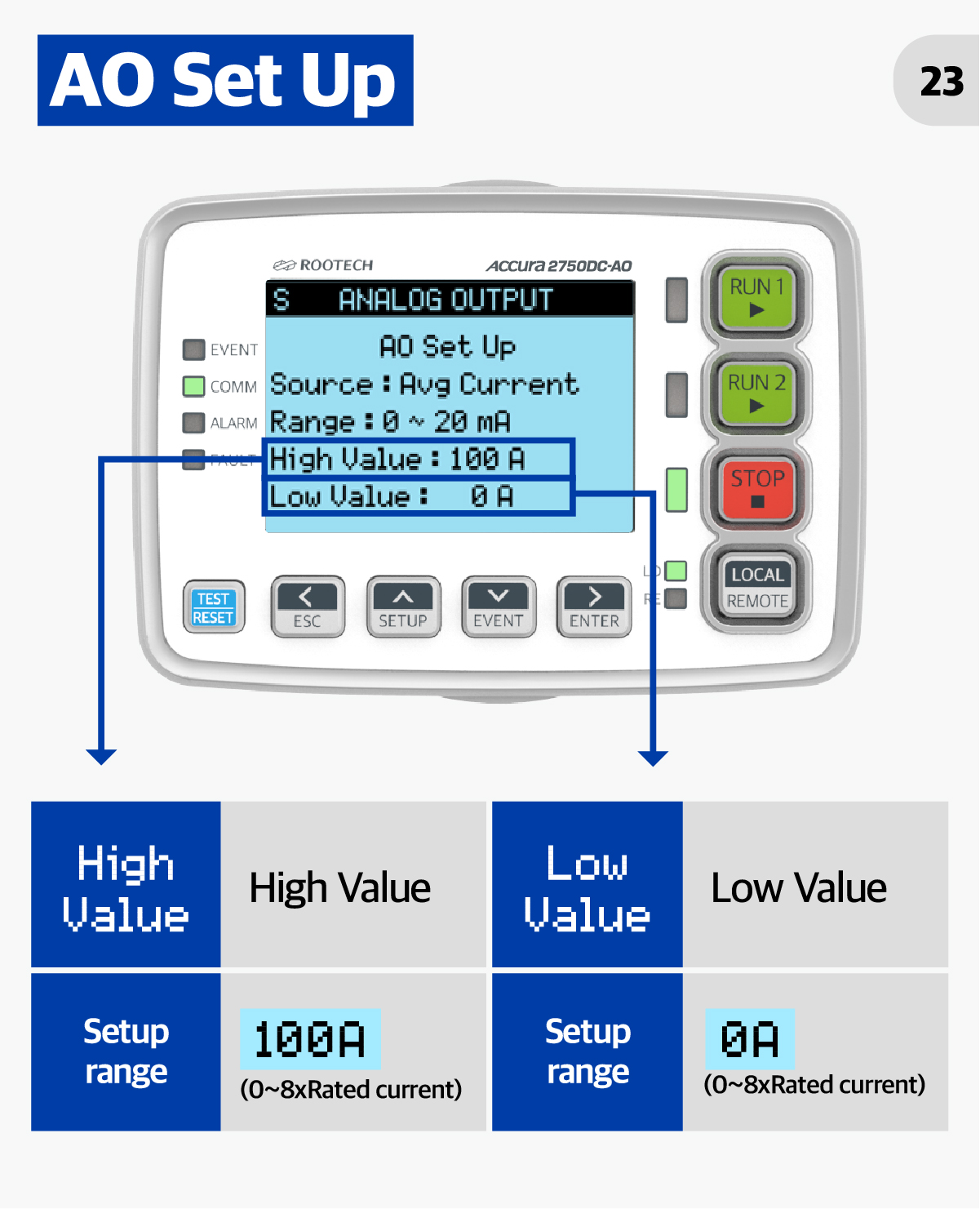
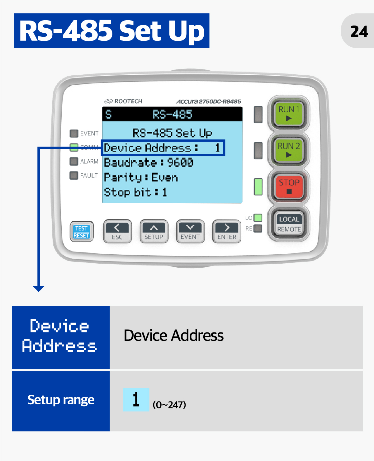
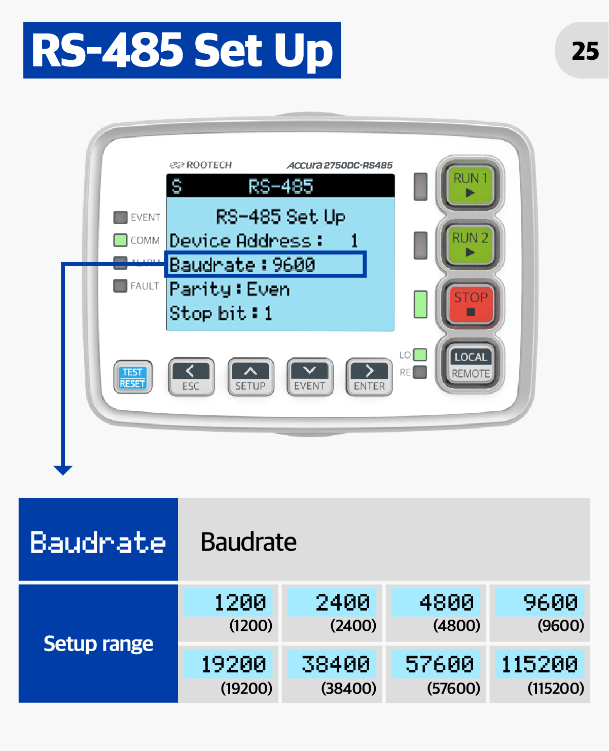
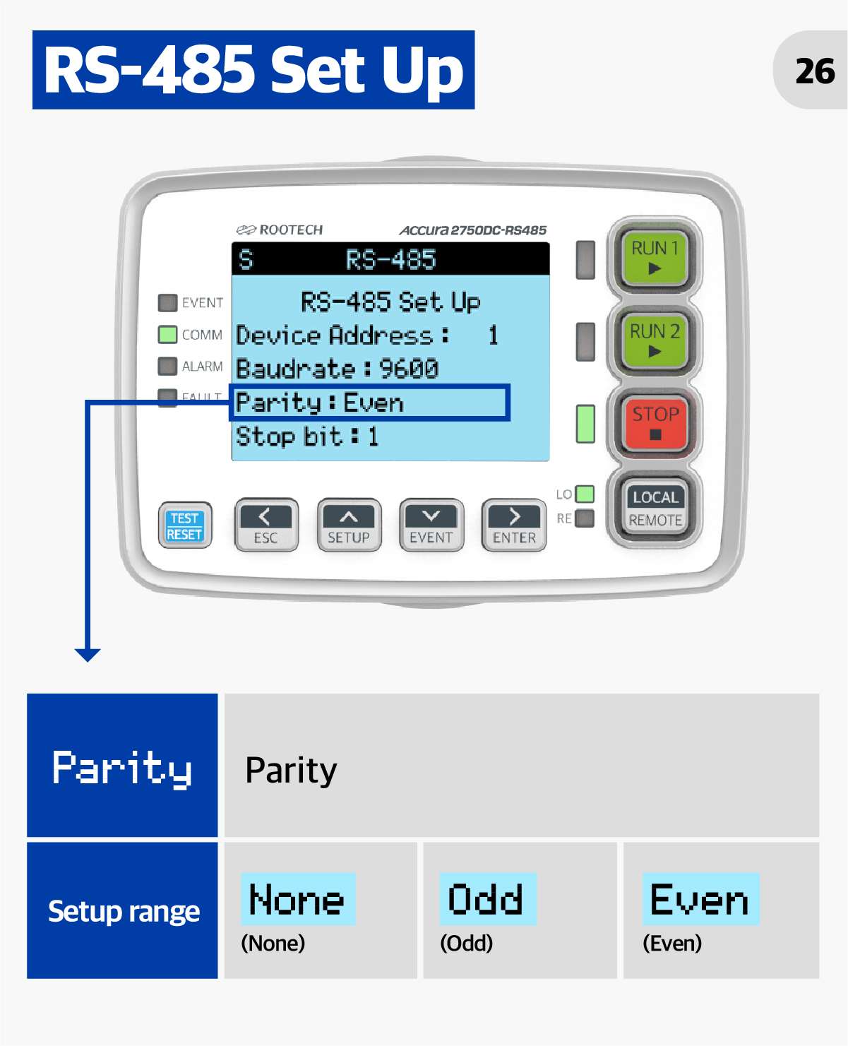
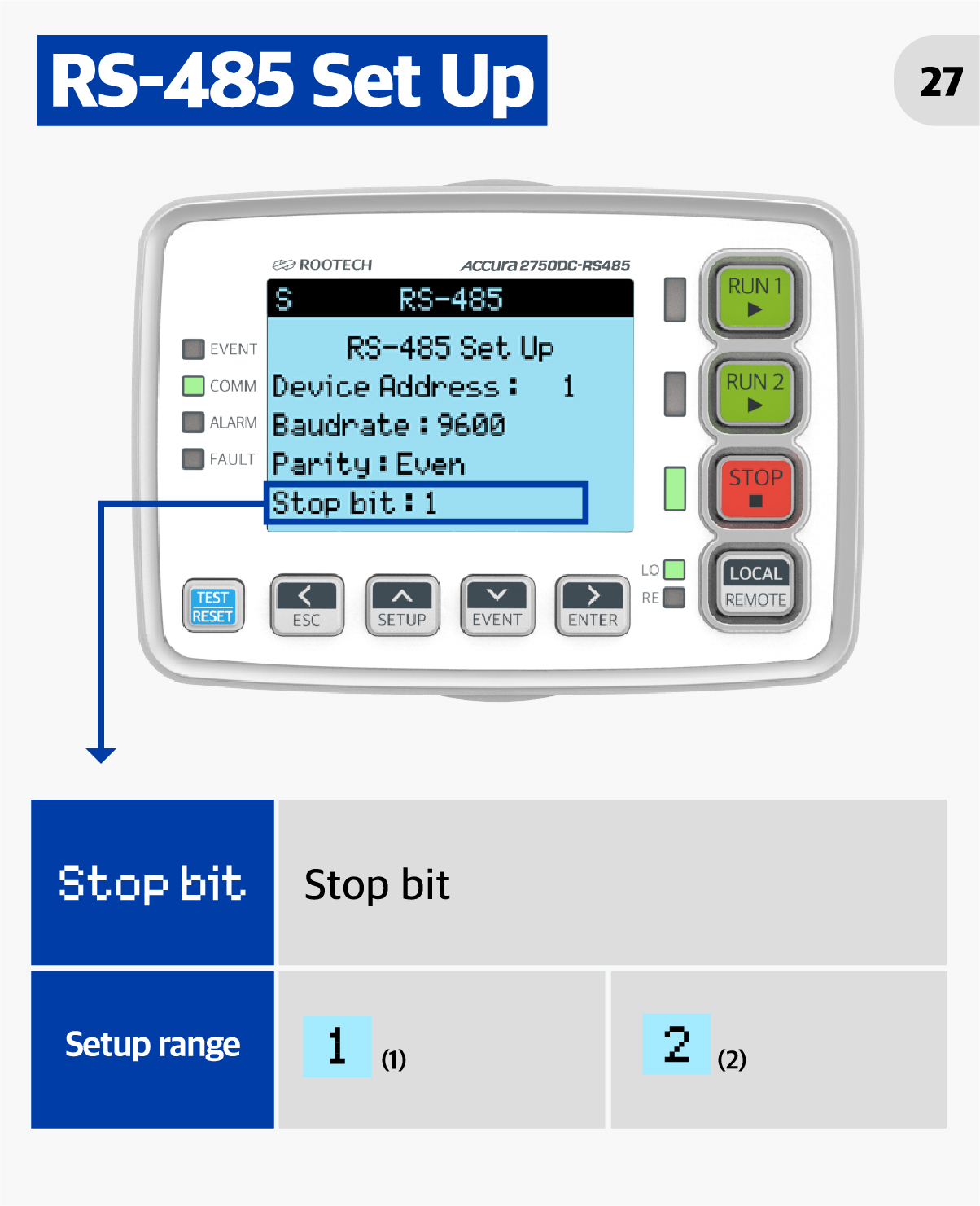
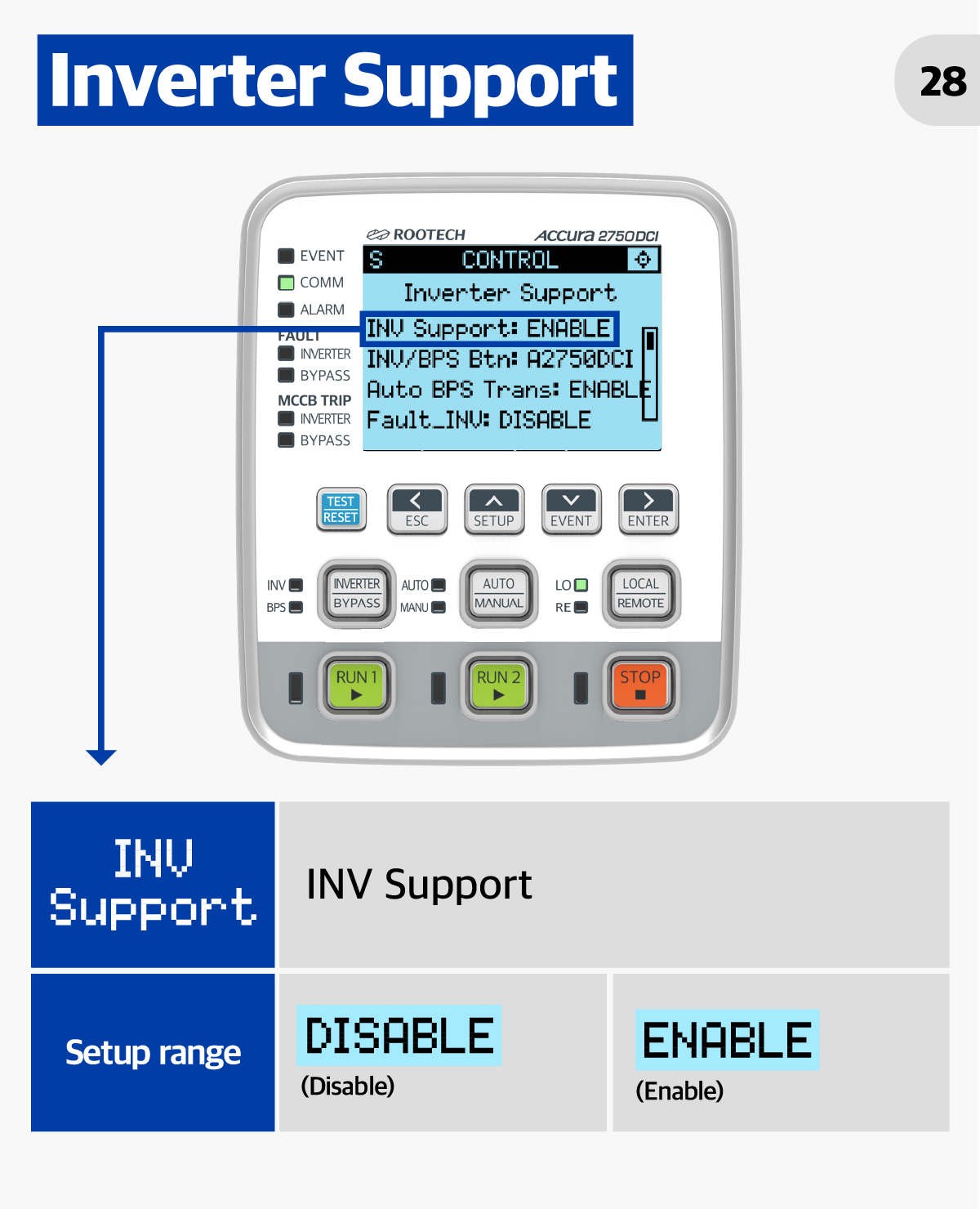
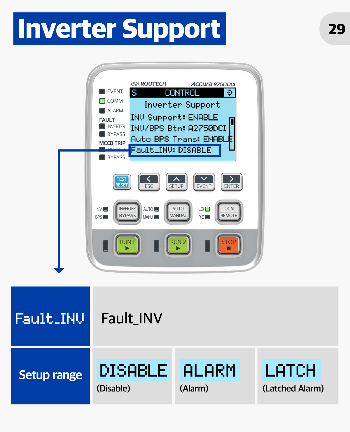

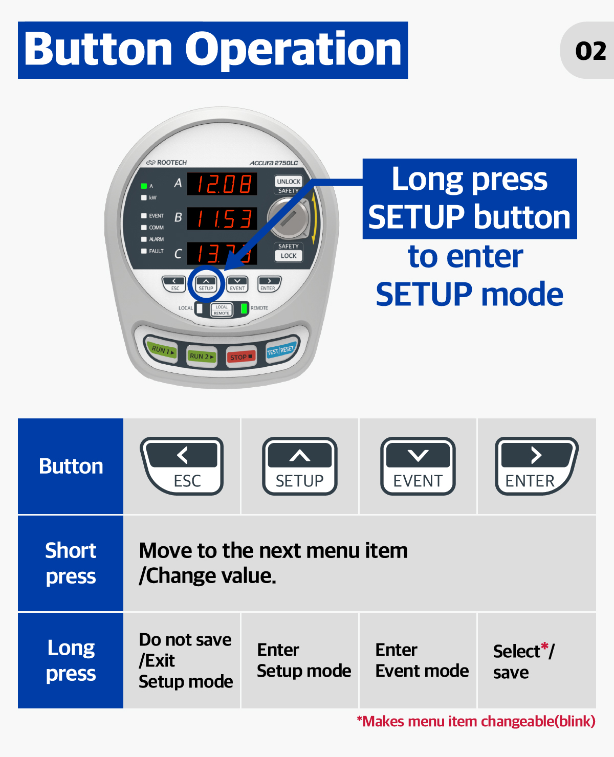
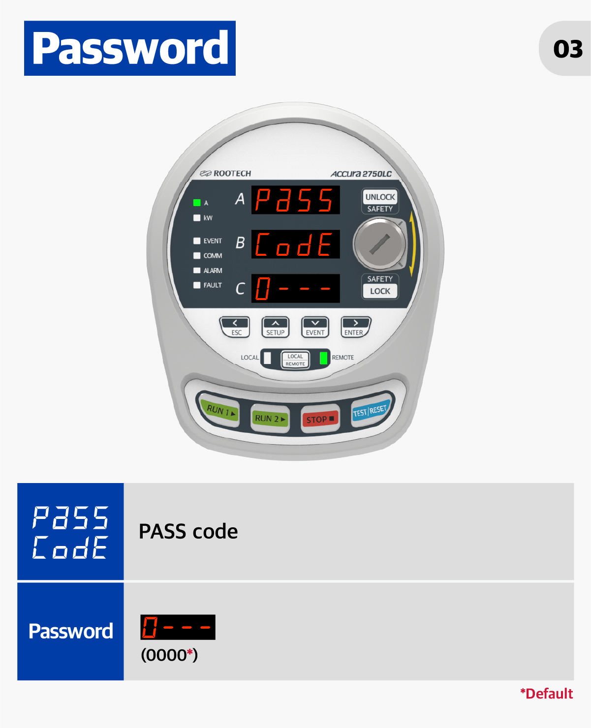
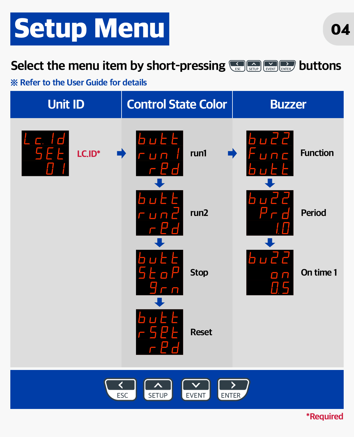
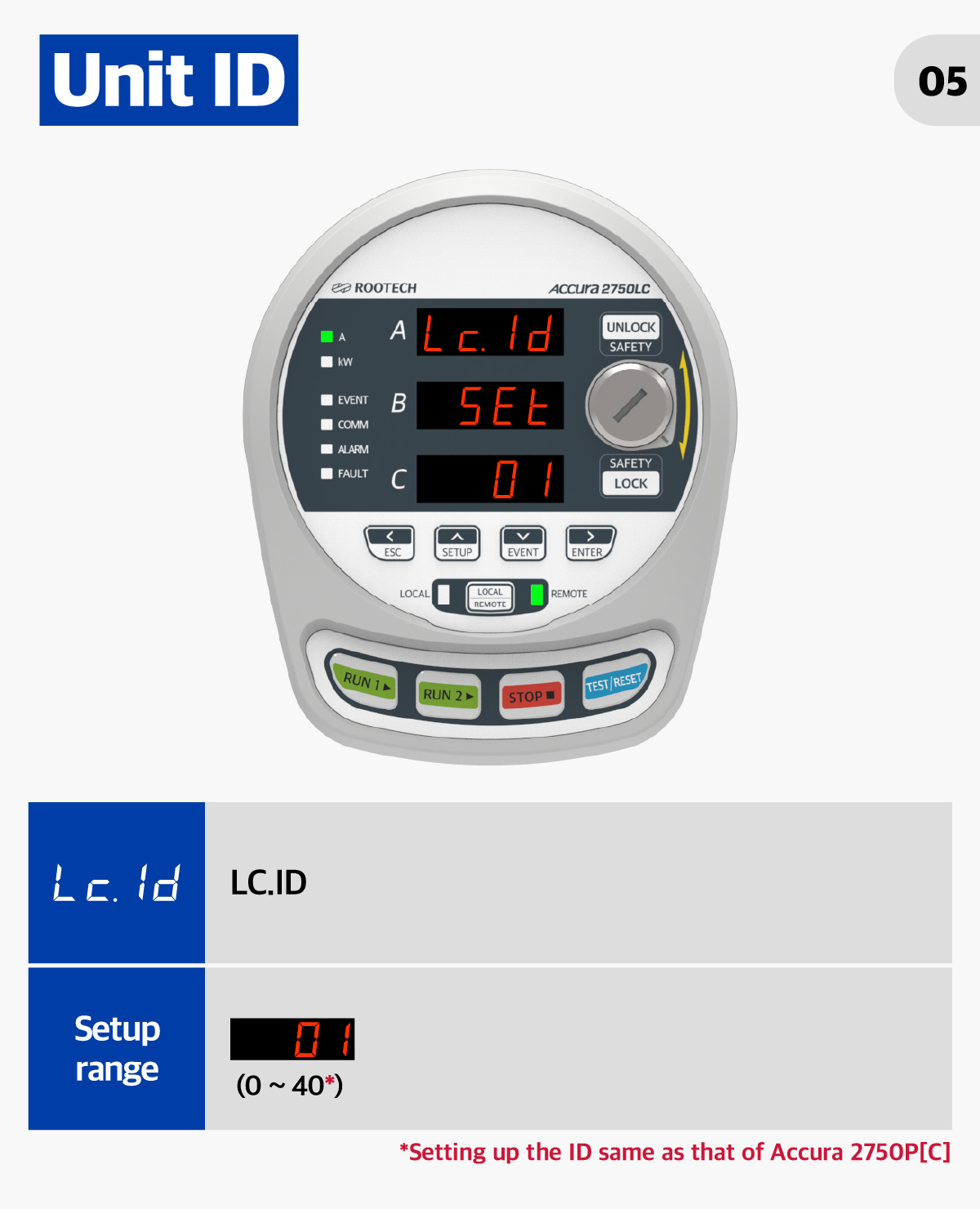


|
|
102-611, 88, Sin won-ro, Yeongtong-gu, Suwon, Gyeonggi-do, Korea TEL 82 31 695 7350 FAX 82 31 695 7399 COPYRIGHT(C)ROOTECH. ALL RIGHTS RESERVED. |
|


